

Wipe and seal product pump
- Summary
- Abstract
- Description
- Claims
- Application Information
AI Technical Summary
Benefits of technology
Problems solved by technology
Method used
Image

Examples
Embodiment Construction
[0029]In the following detailed description, reference is made to the accompanying drawings, which form a part hereof, and in which is shown by way of illustration specific embodiments in which the inventions may be practiced. These embodiments are described in sufficient detail to enable those skilled in the art to practice the invention, and it is to be understood that other embodiments may be utilized and that changes may be made without departing from the spirit and scope of the present invention. The following detailed description is, therefore, not to be taken in a limiting sense, and the scope of the present invention is defined only by the claims and equivalents thereof.
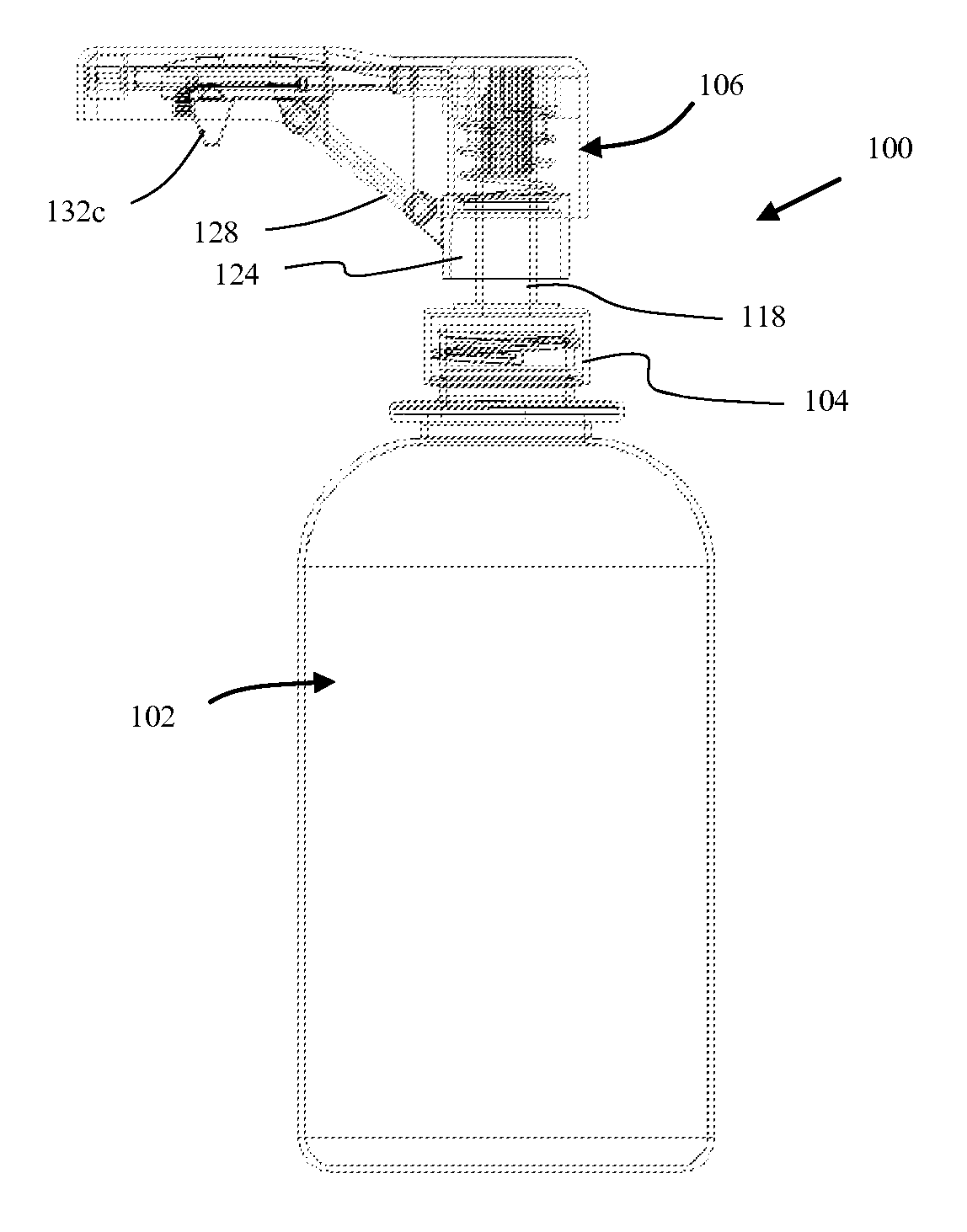
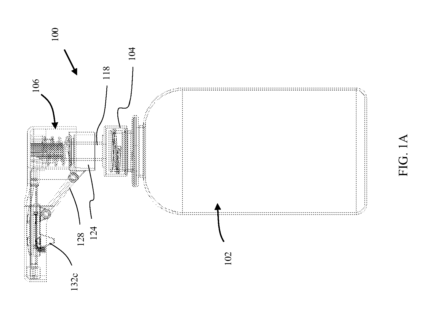
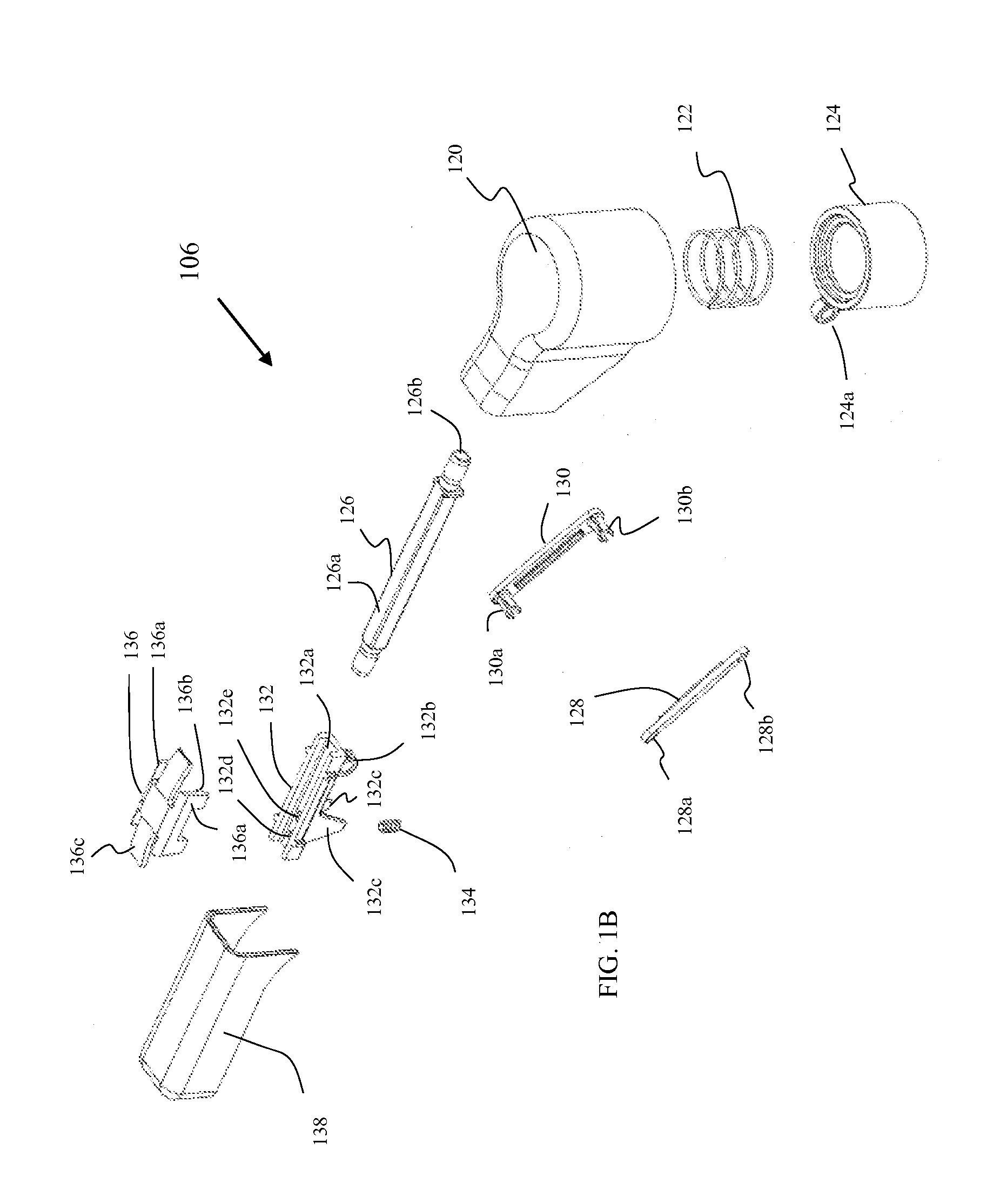
[0030]Embodiments provide dispensing systems that clear product near dispensing orifices and seal the dispensing orifices when not in use. The wipe and seal embodiments are employed when using products that are prone to drying such as, but not limited to, soaps, sanitizers and lotions. In addition, embodiment...
PUM
 Abstract
Description
Claims
Application Information