Operating microscope and method for pivoting a co-observer microscope

a co-observer and microscope technology, applied in the field of operating microscopes, can solve the problems of affecting the use of the beam splitter for decoupling the beam path of the co-observer, and not having the full image brightness, so as to improve the utilization of space and increase the positioning options

Active Publication Date: 2011-02-10
CARL ZEISS MEDITEC AG
View PDF17 Cites 5 Cited by
  • Summary
  • Abstract
  • Description
  • Claims
  • Application Information

AI Technical Summary

Benefits of technology

[0011]In the case of an arrangement of the co-observation pupils between the main observation pupils there is only very little play for twisting the connecting line between the co-observation pupils with respect to the connecting line of the main observer pupils. This play is determined by the distance of the pupils of a pupil pair from one another and by the diameter of the pupils of a pupil pair. Since, as explained at the outset, the observation of the red reflex should be possible where possible for the main observer and the co-observer, the pupils are selected to be as large as possible in order to allow image brightness that is as high as possible. On the other hand, there are limits to the distance between the pupils of a pupil pair by the size of the objective lens, and so operating microscopes according to the prior art are generally designed such that an arrangement of the two pupil pairs with an angle of 90° with respect to one another does not lead to vignetting of the main observer beam path. The invention is now based on the realization that such vignetting can be avoided if the center point between the co-observer pupils in the plane of the main objective is displaced at the same time as at which the angle of intersection between the first and the second imagined lines is changed. This displacement allows better utilization of the space between the two pupils of the main observer beam path. At the same time, the angle between the illumination beam path and the co-observer beam path can be kept small, and so observation of the red reflex also remains possible for the co-observer.
[0012]The first imagined straight line and the second imagined straight line will typically intersect at an angle of 90° in a first position of the co-observer beam path. The displacement arrangement then allows twisting of the second imagined straight line, that is to say the connecting line between the center points of the co-observer pupils, with respect to the first imagined straight line, that is to say the connecting line between the main observation pupils, by an angle of at least 5°, more particularly of at least 10° and preferably of at least 15°. Preferably this allows both clockwise twisting of the second imagined straight line with respect to the first imagined straight line and counterclockwise twisting of the second imagined straight line with respect to the first imagined straight line. The aforementioned play when twisting the co-observer beam path allows optimization of the positioning of the co-observer in relation to the main observer by pivoting the co-observer tube, in which it goes without saying that larger play for twisting significantly increases the positioning options.

Problems solved by technology

However, the use of a beam splitter for decoupling the co-observer beam path is afflicted by the disadvantage of neither the main observer nor the co-observer having the full intensity of the observer beam path, and hence the full image brightness, available to them.
While this only plays a minor role in operations in which work can be undertaken with intensive illumination, the light loss for the main observer and co-observer cannot always be accepted in eye operations in particular.
Light loss by beam splitting is therefore generally undesirable in ophthalmological operating microscopes.

Method used


Image

  • Operating microscope and method for pivoting a co-observer microscope
  • Operating microscope and method for pivoting a co-observer microscope
  • Operating microscope and method for pivoting a co-observer microscope

Examples


Embodiment Construction

[0030]Hereinbelow, FIGS. 1 to 3 are first of all used to explain the underlying principle of the invention before exemplary embodiments of operating microscopes, in which the principle according to the invention has been implemented, are subsequently described.

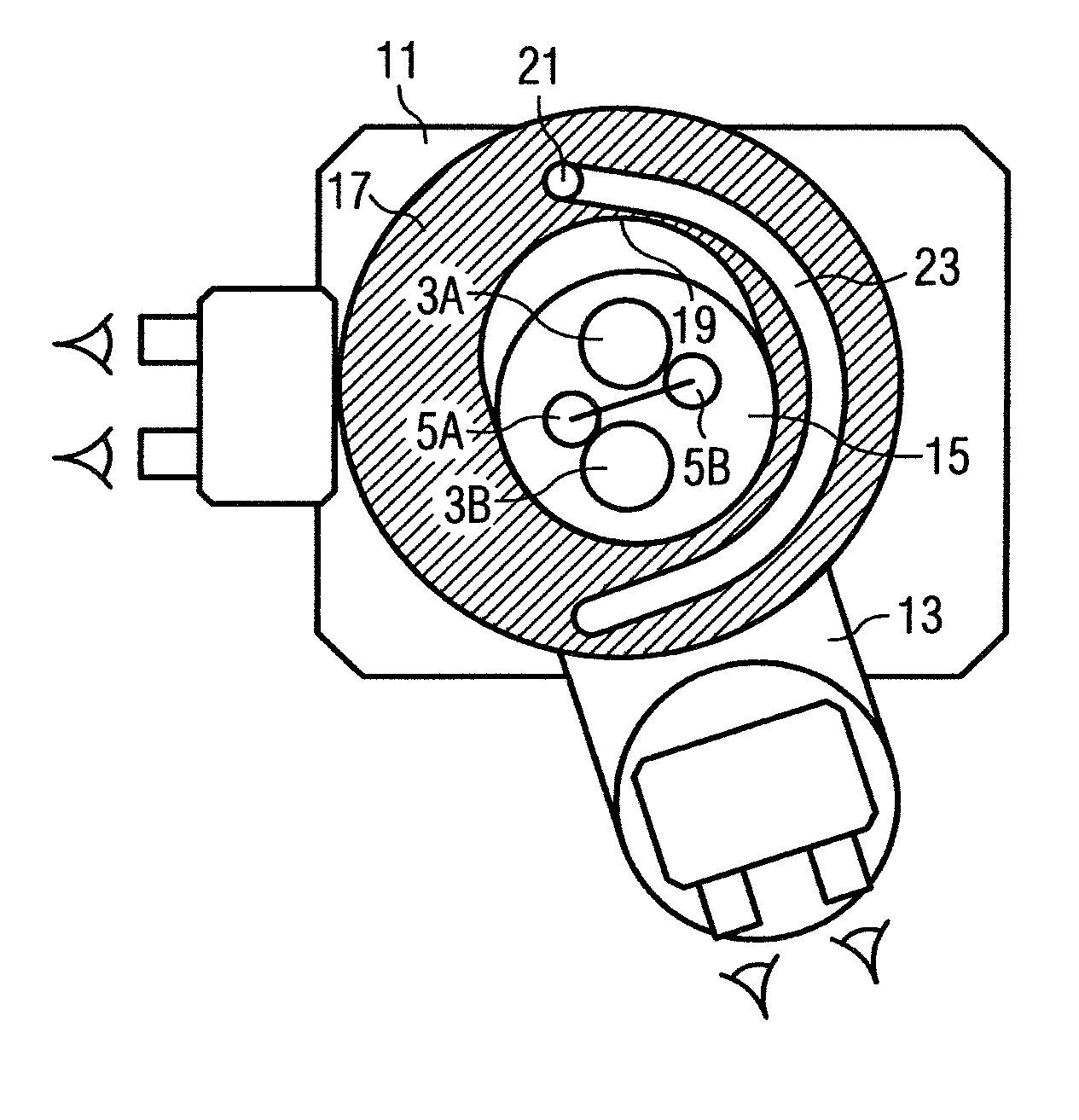
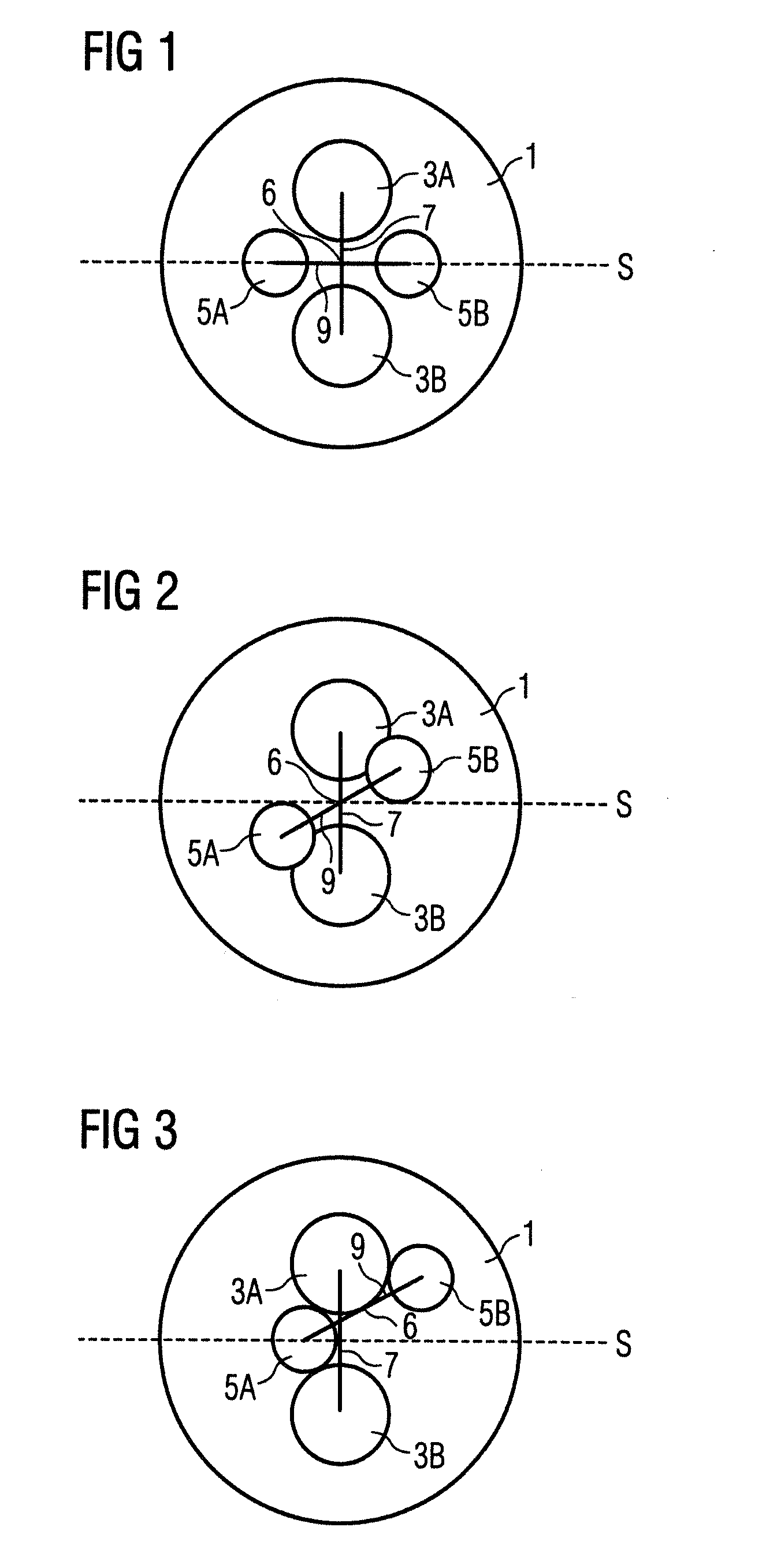
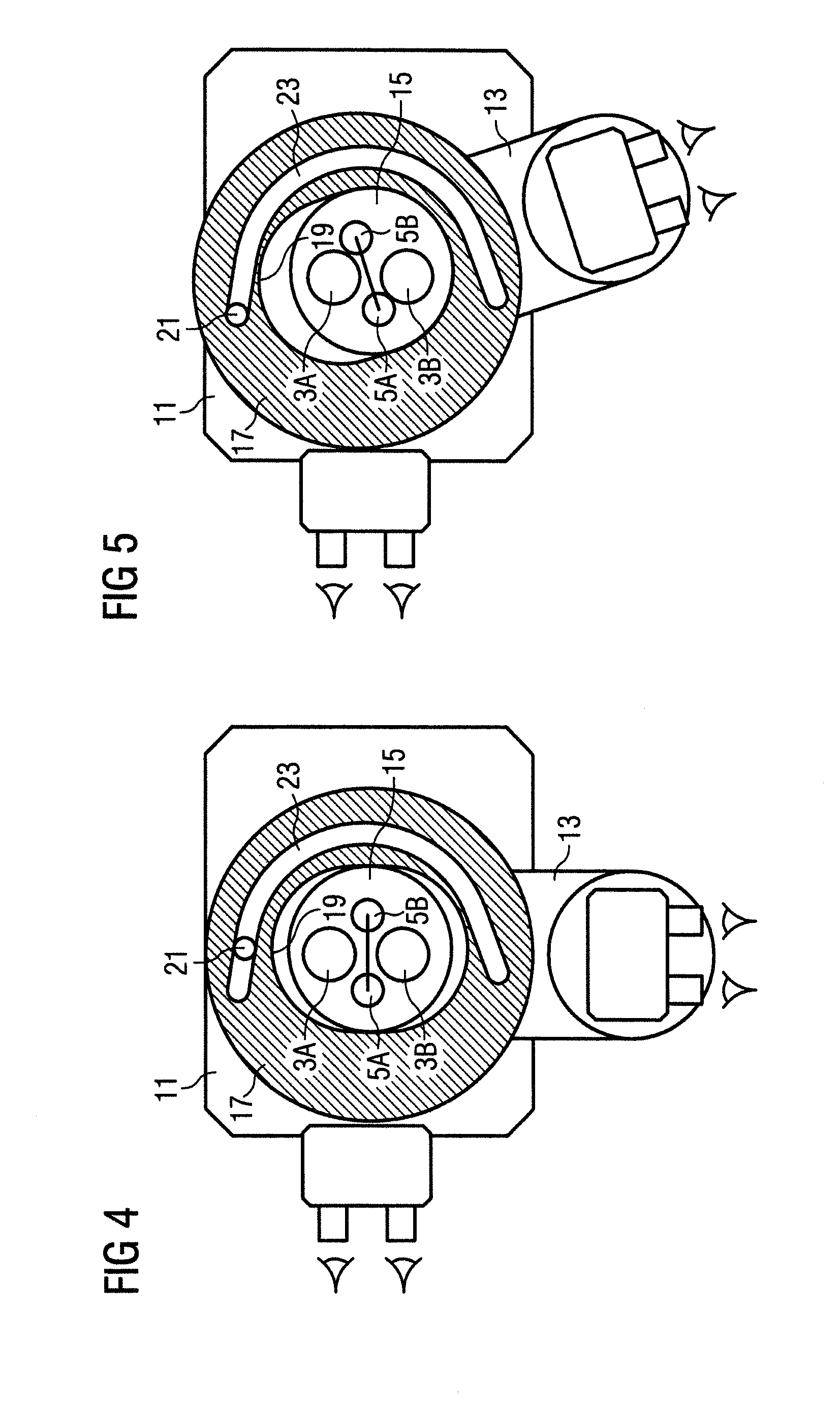
[0031]FIG. 1 shows a section along the objective plane of the main objective 1 of an operating microscope with a main observer microscope and a co-observer microscope, and also shows the observation pupils 3a, 3b of the stereoscopic main observer beam path and the co-observation pupils 5a, 5b of the stereoscopic co-observer beam path. Moreover, imagined connecting lines 7, 9 are indicated, which interconnect the centers of the two main observation pupils 3a, 3b or the two co-observation pupils 5a, 5b.

[0032]The main observation beam path with the main observation pupils 3a, 3b passes through a main observer microscope (not illustrated in FIGS. 1-3), whereas the co-observation beam path with the co-observation pupils 5a, 5b pas...


PUM


Abstract

An operating microscope has a main objective (1) that extends along an objective plane and is penetrated by a binocular main observer beam path and a binocular co-observer beam path. The binocular main observer beam path has two main observation pupils (3a, 3b) in the objective plane with centers on a first straight line (7). The binocular co-observer beam path has two co-observation pupils (5a, 5b) in the objective plane with centers on a second straight line (9). The first and second straight lines (7, 9) intersect. The co-observer beam path can be displaced with respect to the main observer beam path so that the angle between the second and first straight line (9, 7) changes. The center point (6) between the co-observation pupils (5a, 5b) in the objective plane displaces when there is a change in the angle between the second and first imagined straight lines (9, 7).

Description

BACKGROUND OF THE INVENTION[0001]1. Field of the Invention[0002]The present invention relates to an operating microscope with a main objective that extends along an objective plane and is penetrated by a binocular main observer beam path and a binocular co-observer beam path. Additionally, the invention relates to a method for pivoting a co-observer microscope around a main observer microscope.[0003]2. Description of the Related Art[0004]During surgery carried out with the aid of an operating microscope, it is often desirable, or even necessary, for an assistant of the treating surgeon to likewise be able to observe the operation site in an enlarged fashion through the operating microscope. It is for this reason that operating microscopes are often equipped with a binocular tube for an assistant, the so-called assistant tube or co-observer tube, also referred to as co-observer microscope, in addition to a binocular tube for the main observer, the so-called main observer tube or main...

Claims


Application Information

Patent Timeline
Patent Type & Authority Applications(United States)
IPC IPC(8): G02B21/22G02B21/20
CPCG02B21/22A61B19/5223A61B90/20
Inventor ABELE, ALFONSDEMLEITNER, RUPERTKOLSTER, DANIEL
Owner CARL ZEISS MEDITEC AG
Why Eureka
Try Eureka