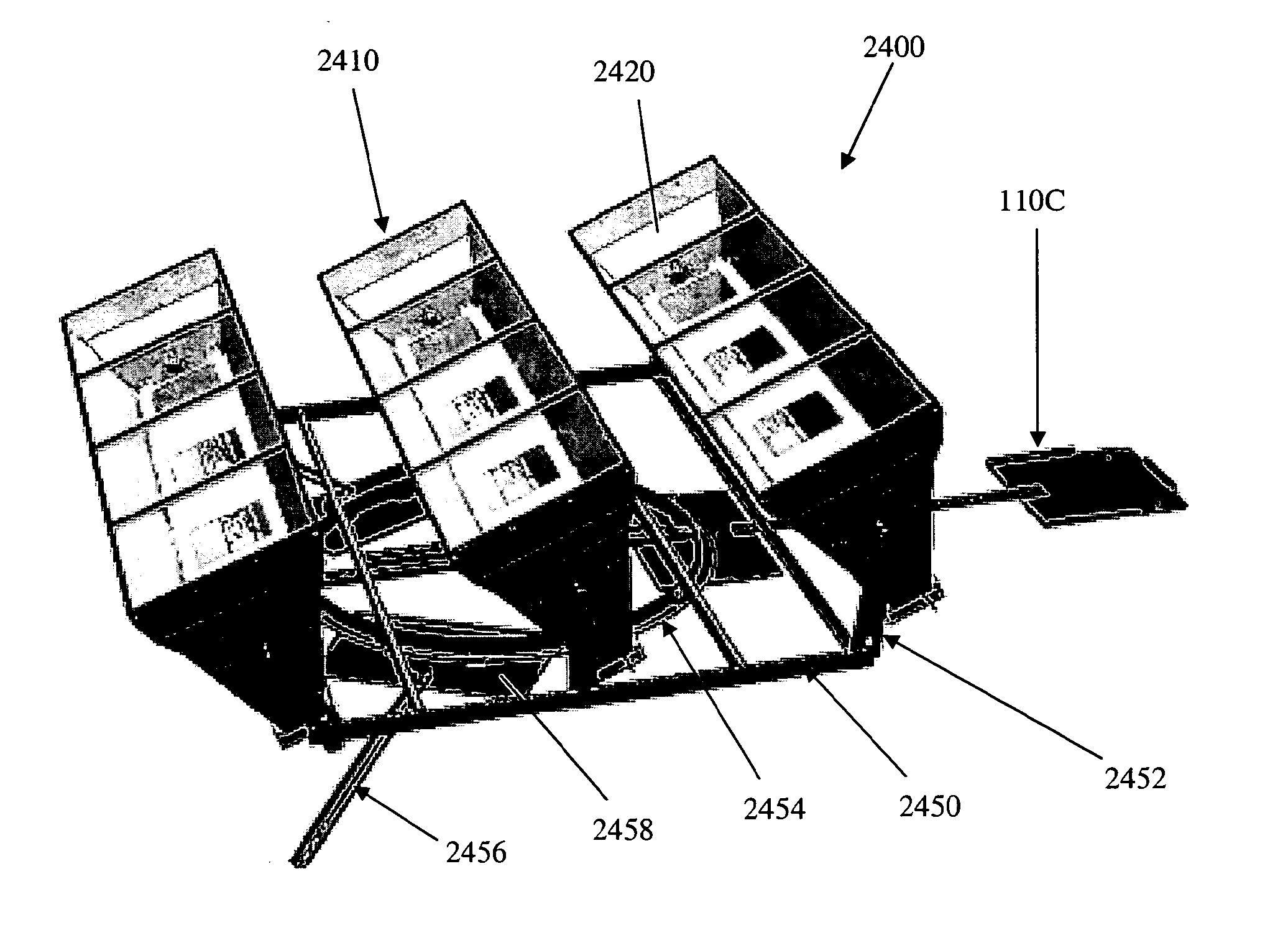
Solar collector mounting array
a technology for solar collectors and mounting arrays, which is applied in the direction of solar heat collectors, solar heat collector safety, heat collector mounting/support, etc., can solve the problems of reducing the likelihood of the base assembly moving or otherwise shifting on the roof, unable to re-roof or resurface, and exposing the roof to damag
- Summary
- Abstract
- Description
- Claims
- Application Information
AI Technical Summary
Benefits of technology
Problems solved by technology
Method used
Image
Examples
first embodiment
[0064]In some preferred embodiments, the frame of the solar energy concentrator is made to frictionally adhere to a roof using a plurality of footings that distribute the weight of the concentrator and increase the friction inhibiting the concentrator from sliding across the roof under the force of gravity or wind loading or combinations thereof. As illustrated in FIGS. 21A-21C, the heliostat chassis includes a plurality of frame support feet 308, each foot 308 being detachably affixed to a footing that directly engages the roof. In the footing, the footing includes a hollow container 1100 adapted to receive ballast and means to detachably engage the container 1100 to the leg 308. The hollow footing includes a bayonet fitting or threaded mouth 1104 and cap 1105, for example, adapted to receive ballast 1120—preferably water, sand, or gravel-retained within a reservoir therein. As illustrated in the cross section of the hollow footing in FIG. 21C, the means to detachably engage the le...
second embodiment
[0066]As illustrated in FIGS. 22A and 22B, a concentrator footing includes a subassembly as a means to detachably engage the leg 308 and solid ballast. The exemplary subassembly includes a post 1204 that slidably engages the leg and a bottom plate 1208 for bearing the weight of the sold ballast 1202. As described above, the post detachably engages heliostat leg 308 by means of pins 1206A, 1206B outwardly biased by a spring 1206C. The ballast may be concrete although various other materials, preferably durable and having a relatively high density may also be employed.
third embodiment
[0067]Illustrated in FIGS. 23A and 23B is a concentrator footing. Each of the one or more footings 1300 is a receptacle including a cavity adapted to receive ballast such as an 8 inch cinder block 1310, for example. The footings 1300 are attached to the concentrator by means of fasteners, e.g., bolts, that engage the mounting plate 1308 Movement of the concentrator is inhibited by the cinder block which enhanced the weight and static friction of the via the inner wall 1304 and bottom plate 1306 made of rigid material. Preferably, the outer wall 1302 is inclined to mitigate the force of wind or to induce downward pressure on the footings for purposes of increasing static friction with the underlying roof.
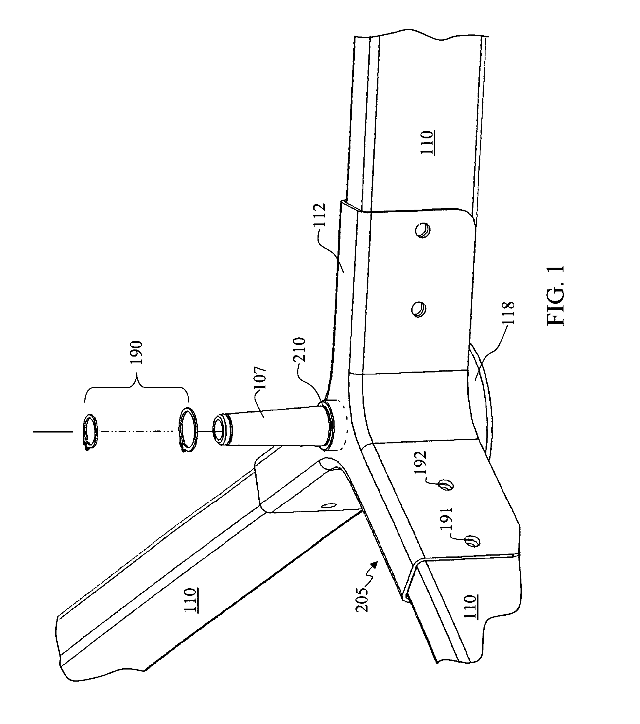
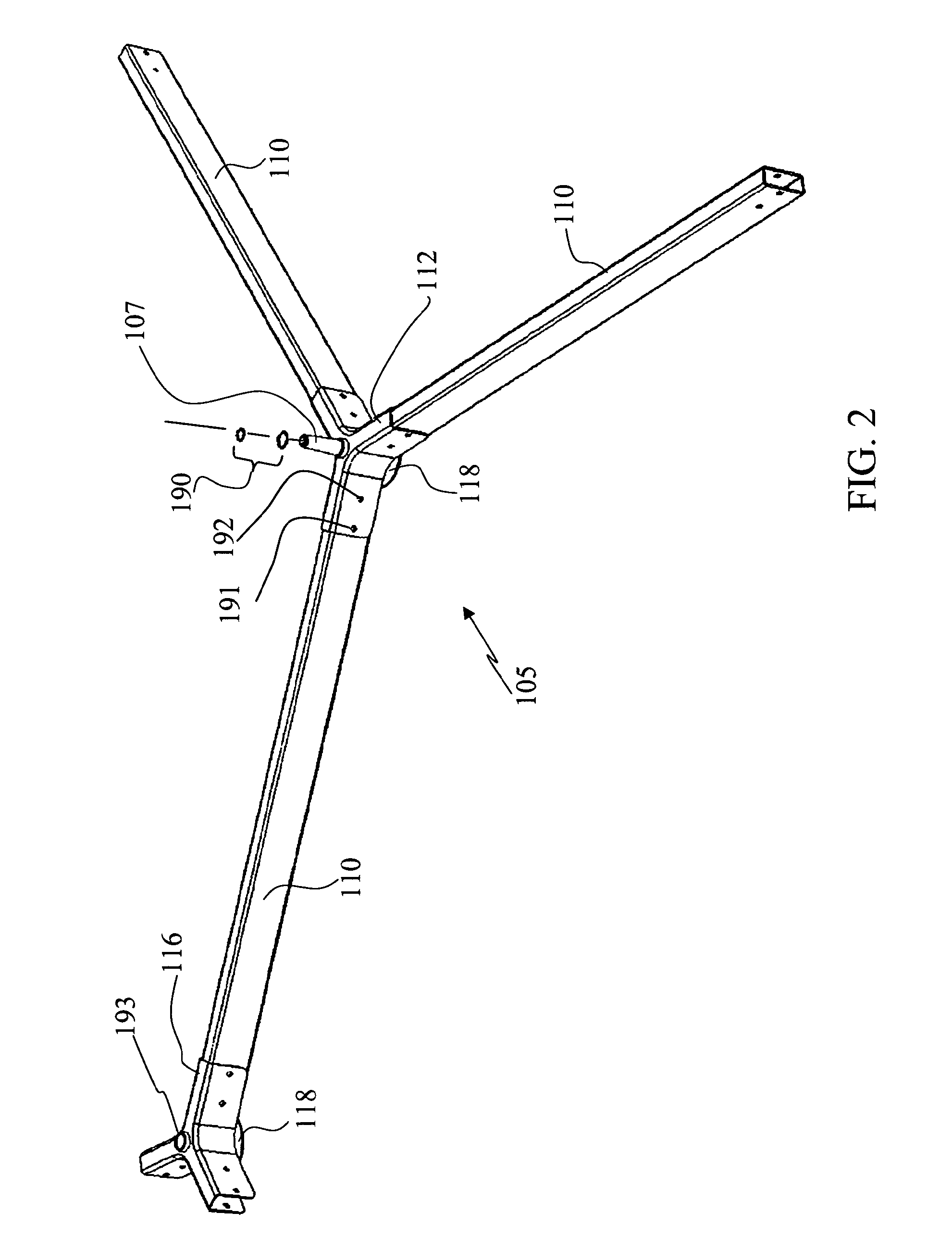
[0068]In addition, the several embodiments of the system of solar collector support structures may be used to secure the heliostat to a mounting surface. For example, junction elements having three or four arms or leg receivers may form three-leg or four-leg base assemblies respectiv...
PUM
 Abstract
Description
Claims
Application Information
 - R&D
- Intellectual Property
- Life Sciences
- Materials
- Tech Scout
- Unparalleled Data Quality
- Higher Quality Content
- 60% Fewer Hallucinations
Browse by: Latest US Patents, China's latest patents, Technical Efficacy Thesaurus, Application Domain, Technology Topic, Popular Technical Reports.
© 2025 PatSnap. All rights reserved.Legal|Privacy policy|Modern Slavery Act Transparency Statement|Sitemap|About US| Contact US: help@patsnap.com


