Apparatus and method for high spatial resolution imaging of a structure of a sample

a high spatial resolution, sample technology, applied in the direction of lighting and heating apparatus, instruments, photometry, etc., can solve the problems of limiting the optical resolution that can be achieved in the conventional spim method, overlapping airy disks still present, and cannot be evaluated, so as to reduce the out-of-focus autofluorescence, the effect of high resolution and high image ra

Active Publication Date: 2011-02-17
CARL ZEISS MICROSCOPY GMBH
View PDF6 Cites 81 Cited by
  • Summary
  • Abstract
  • Description
  • Claims
  • Application Information

AI Technical Summary

Benefits of technology

[0030]The object of the invention is to avoid the disadvantages of the methods described above. The invention describes a method and arrangement for realizing a PALM microscope with optimized photoactivation for realizing a higher image rate. Compared to PALM, a high resolution with three-dimensional imaging is achieved without nonlinear photoactivation. A PALM / TIRF combination for reducing the out-of-focus autofluorescence is not required. The multi-view method (a plurality of illumination angles on the sample) can advantageously be used to achieve an increased depth of penetration and an isotropic optical resolution in x, y, and z.

Problems solved by technology

As a rule, its extent is determined by the lateral resolution of the detection lens that is used, which generally limits the optical resolution that can be achieved in the conventional SPIM method.
However, overlapping Airy disks are still present and cannot be evaluated ((3) in FIG. 1b).
There are difficulties involved in applying the PALM method in three-dimensional imaging because molecules outside of the focus plane are also activated and are therefore bleached and their fluorescent light cannot be used for imaging.
This hinders the recording of a z-scan so that three-dimensional imaging of the sample cannot be achieved.
However, the technology is complicated in this arrangement.
For example, the dyes (PA-GFP) must be nonlinearly activatable and high intensities must be used which can result in damage to the dye or sample.
However, three-dimensional imaging is not possible with TIRF.
In general, these are point-scanning methods having disadvantages with respect to fast data acquisition.
Further, the sample is unnecessarily stressed in out-of-focus regions.
It is also considered disadvantageous in these methods that the sample is unnecessarily stressed in out-of-focus regions because the structured illumination is performed throughout the entire sample space.
Further, the method cannot currently be used with thick samples because the fluorescence excited outside of the focus reaches the detector as a background signal and accordingly reduces the dynamic range.

Method used


Image

  • Apparatus and method for high spatial resolution imaging of a structure of a sample
  • Apparatus and method for high spatial resolution imaging of a structure of a sample
  • Apparatus and method for high spatial resolution imaging of a structure of a sample

Examples


Embodiment Construction

[0040]It is to be understood that the figures and descriptions of the present invention have been simplified to illustrate elements that are relevant for a clear understanding of the present invention, while eliminating, for purposes of clarity, many other elements which are conventional in this art. Those of ordinary skill in the art will recognize that other elements are desirable for implementing the present invention. However, because such elements are well known in the art, and because they do not facilitate a better understanding of the present invention, a discussion of such elements is not provided herein.

[0041]The present invention will now be described in detail on the basis of exemplary embodiments.

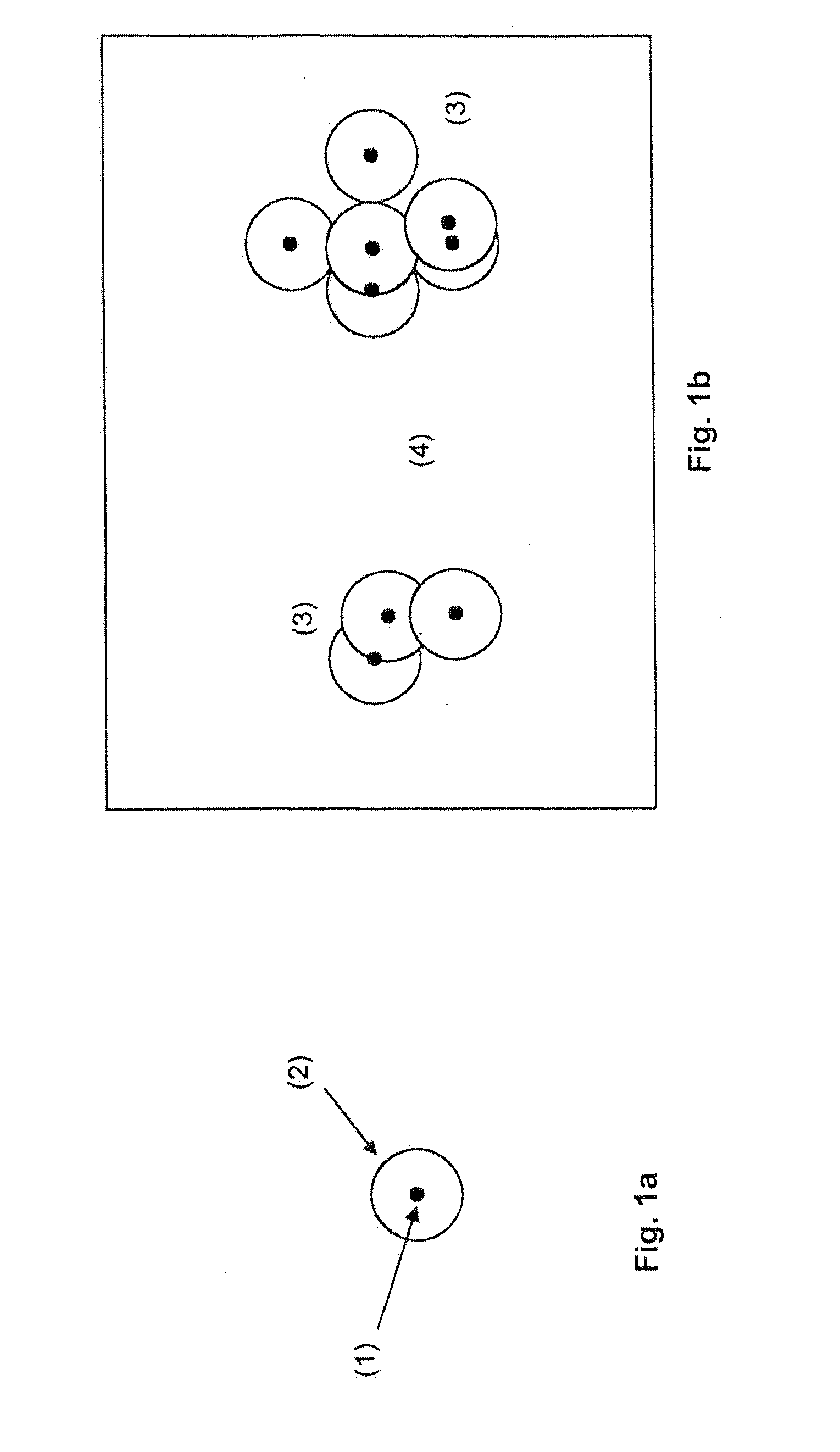
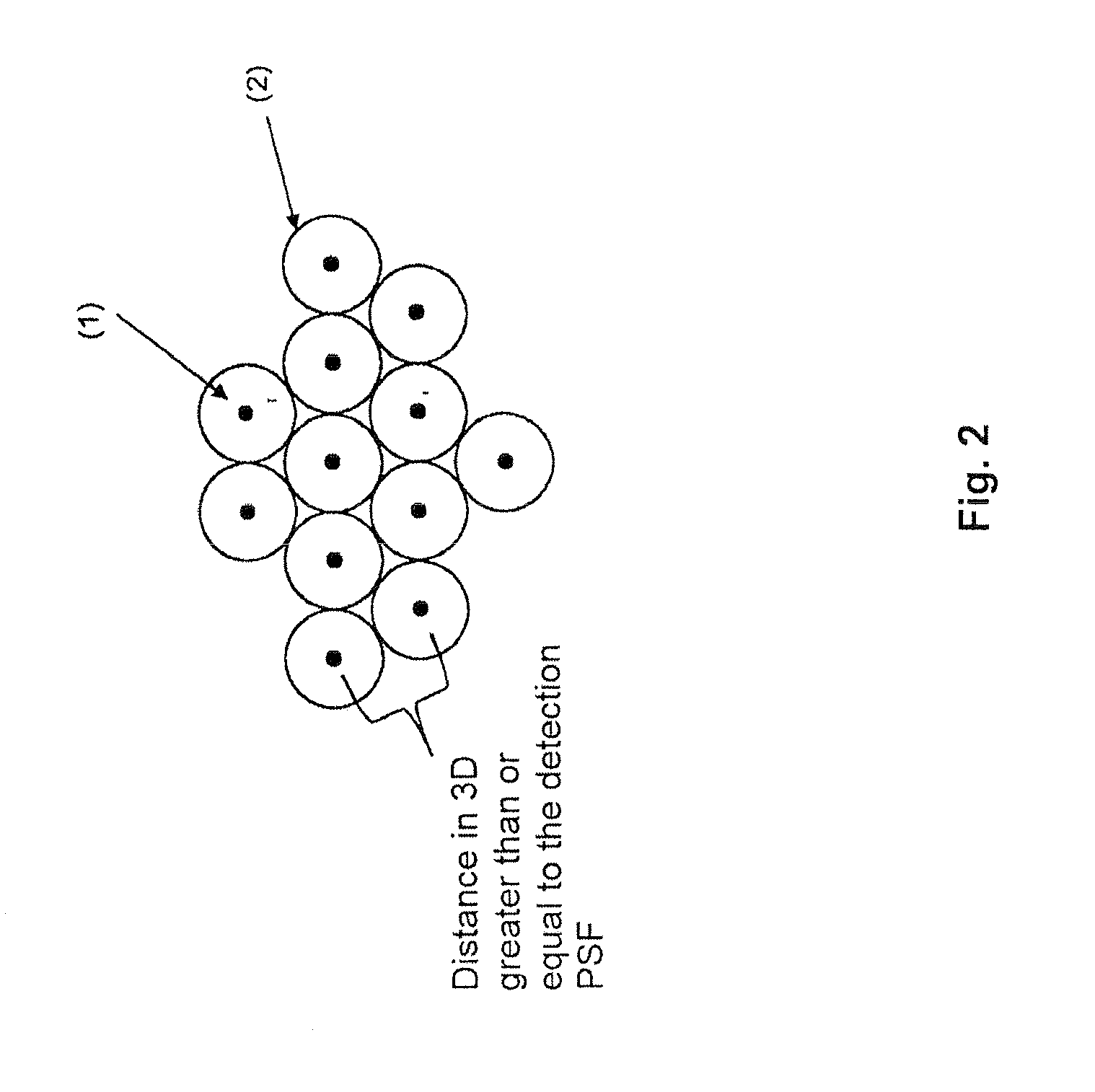
[0042]As many molecules as possible are activated, according to FIG. 2, without “gaps” ((4) in FIG. 1b) and without the Airy disks of the molecules overlapping on the camera ((3) in FIG. 1b). If the Airy disks of the individual molecules are set end to end, there is preferably ...


PUM


Abstract

Apparatus and method for high spatial resolution imaging of a sample's structure, including a diffraction-limited resolution volume with a plurality of dye molecules which can be switched between different states and have a distribution density which is greater than the inverse of the diffraction-limited resolution volume, where at least one state is fluorescing, the fluorescence being collected by an objective lens and imaged on a spatially resolving detector by an optical system. At least one light source provided for emitting a switching radiation and for emitting an excitation radiation. At least one of the light sources is arranged to radiate through the sample, and a switching and/or fluorescence excitation of the dye molecules is carried out. The switching is a photoactivation or a photodeactivation of the dye molecules. A focusing arrangement is provided for switching and/or for excitation to generate a line-like illumination region extending in a direction of illumination.

Description

[0001]The present application claims priority from PCT patent application No. PCT / EP2009 / 000677 filed on Feb. 3, 2009, which claims priority from German Patent Application No. DE 10 2008 009 216.9 filed on Feb. 13, 2008, the disclosure of which is incorporated herein by reference in its entirety.BACKGROUND OF THE INVENTION[0002]1. Field of the Invention[0003]The invention is directed to a method and arrangement for realizing a PALM microscope with optimized photoactivation for realizing a higher image rate.[0004]2. Description of Related Art[0005]Selective plane illumination microscopy (SPIM) has been described as a microscopy method, for example, in Stelzer et al. [1-4]:[0006][1] Stelzer et al., Optics Letters 31, 1477 (2006).[0007][2] Stelzer et al., Science 305, 1007 (2004).[0008][3] DE 102 57 423 A1[0009][4] WO 2004 / 0530558 A1[0010]Like confocal laser scanning microscopy, SPIM, as a widefield technique, allows three-dimensional objects to be recorded in the form of optical secti...

Claims


Application Information

Patent Timeline
Patent Type & Authority Applications(United States)
IPC IPC(8): G01J1/58
CPCG01N21/6458G02B27/58G02B21/10G02B21/002G02B21/367
Inventor WOLLESCHENSKY, RALFLIPPERT, HELMUTPOWER, CHRISTOPHERRADT, BENNO
Owner CARL ZEISS MICROSCOPY GMBH
Why Eureka
Try Eureka