
Blow moulding machine with cleaning system

a cleaning system and blow moulding machine technology, applied in the field of blow moulding machines with cleaning systems, can solve the problems of reducing the cooling effect of the mould surface, affecting the quality of the bottle, and dulling of the surface of the blow mould

Inactive Publication Date: 2011-02-17
KRONES AG
View PDF5 Cites 41 Cited by
  • Summary
  • Abstract
  • Description
  • Claims
  • Application Information

AI Technical Summary

Benefits of technology

The patent describes an apparatus for transforming plastic preforms into containers. The apparatus includes a blow mold, a pressure application device, and a cleaning device. The cleaning device can clean the blow mold while it is in operation, allowing for continuous cleaning without stopping the operation of the apparatus. The cleaning device can also apply a sterilizing medium to the blow mold to avoid corrosion damage. The apparatus can also have a reservoir for the sterilizing medium and a rotary distributor for even distribution of the cleaning agent. The blow mold can have separate side parts that can be opened and closed, and the outlet opening can be located in the bottom part of the blow mold or in the pressure application device. The apparatus can also have a plurality of outlet openings or nozzles for more effective cleaning. Overall, the apparatus provides a more efficient and automated way to clean and sterilize the blow mold.

Problems solved by technology

The surface of these blow moulds therefore becomes dull and in the extreme case rough as it becomes increasingly soiled.
However, this has negative effects on the bottle quality, since this may lead to the situation whereby the bottle appearance may become cloudy on account of the dull blow moulds or else the cooling on the mould surface is reduced as a result of the roughness.
Since both of these problems are unacceptable, the blow moulds must be cleaned and usually polished at regular intervals.
Particularly high degrees of soiling by oligomers occur when working with high mould temperatures for process reasons (e.g. in the case of hot fill processes), since soiling is much faster with hot moulds and the cleaning of the moulds in the hot state can be carried out only with a safety risk due to the risk of burning.
Particularly in the case of a so-called hot filling installation with a blow moulding machine and a filler block, this cleaning of the moulds is often a very negative aspect.

Method used


Image

  • Blow moulding machine with cleaning system
  • Blow moulding machine with cleaning system
  • Blow moulding machine with cleaning system

Examples


Embodiment Construction

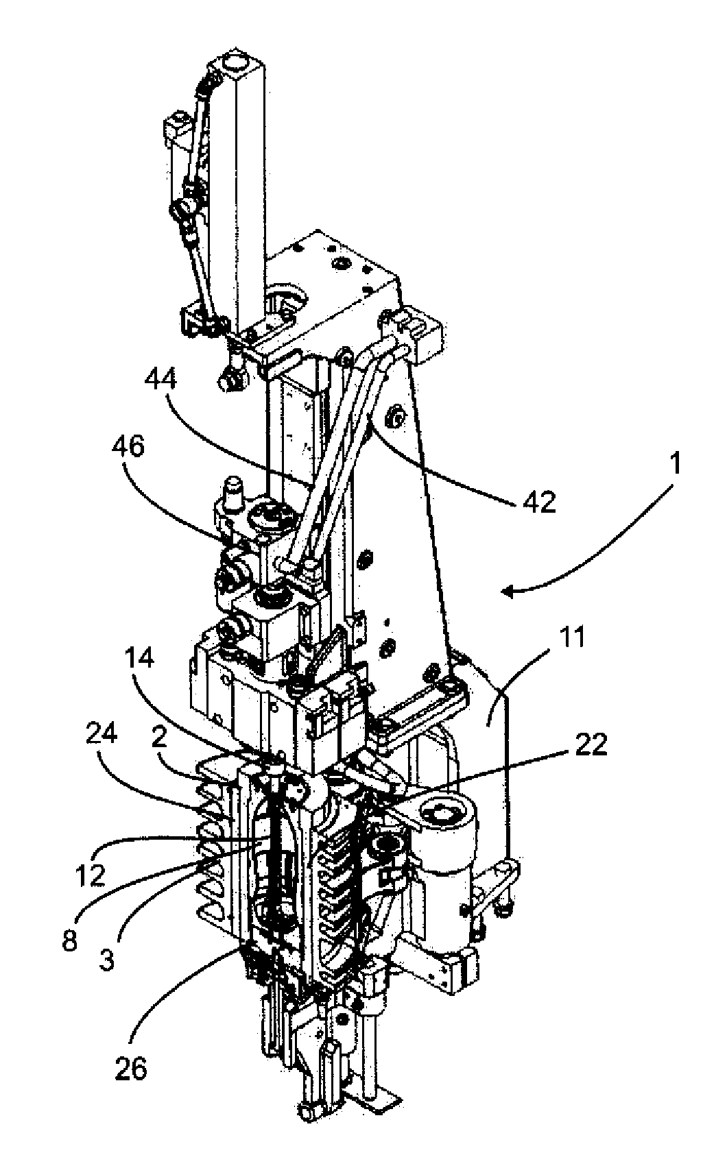
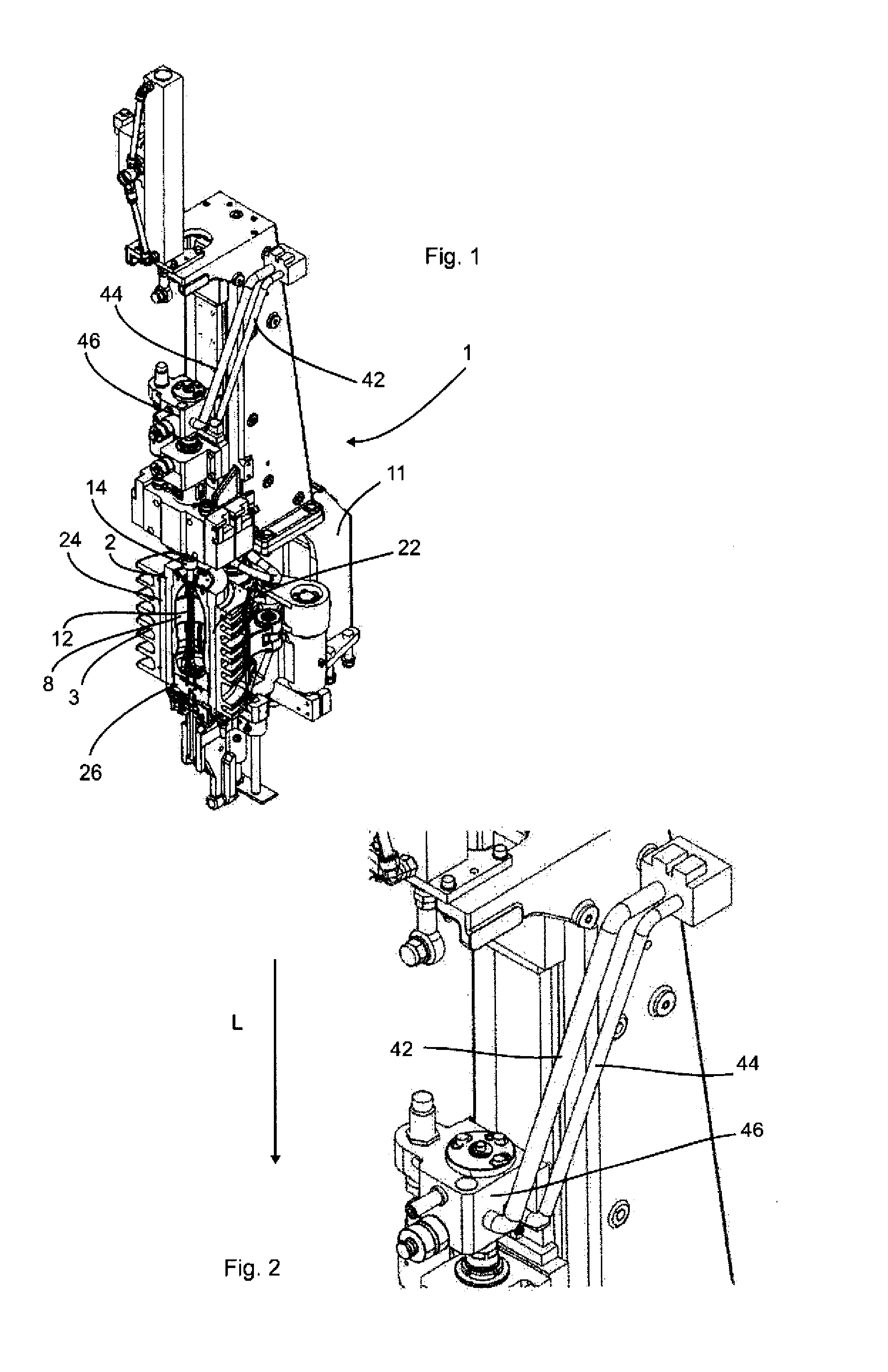
[0051]FIG. 1 shows an apparatus according to the invention for transforming plastic preforms (not shown) into plastic containers (not shown). This apparatus comprises a main carrier 11, on which a blow mould 2 is arranged in a blow mould carrier 3 (in each case shown only partially).

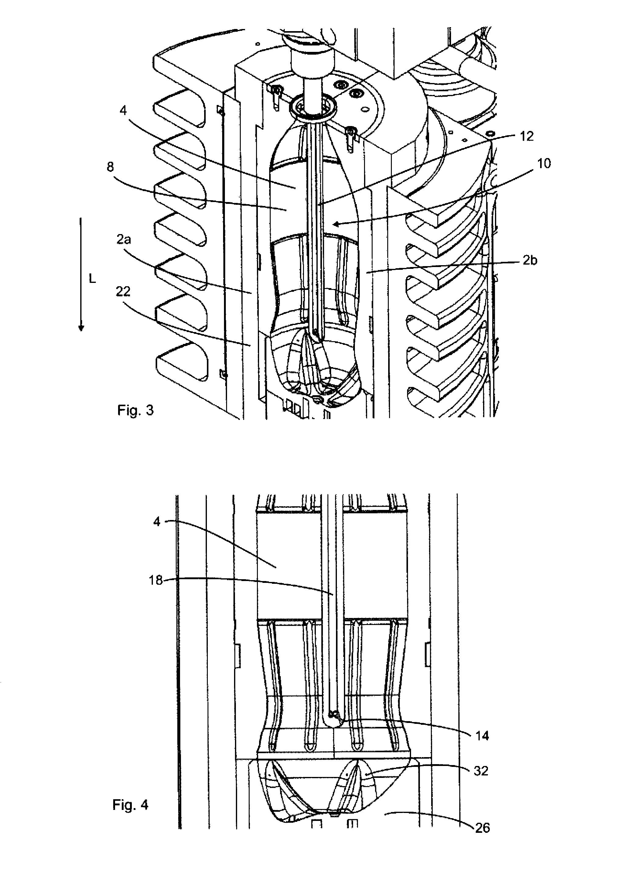
[0052]Formed inside the blow mould 2 is a cavity 4, inside which the plastic preforms are expanded through the application of compressed air to form plastic containers. Furthermore, the apparatus comprises a stretching rod 12, which is movable here in the longitudinal direction L, for stretching the plastic preforms. Reference 22 denotes a first blow mould half and reference 24 denotes a second blow mould half. In addition, the blow mould also has a bottom 26 or a bottom part, which closes the cavity 4 in the downward direction during operation. Reference 14 denotes a pressure application device or blowing nozzle which applies compressed air to the plastic preforms.

[0053]In the embodiment shown in FIG. 1...


PUM

PropertyMeasurementUnit
pressureaaaaaaaaaa
roughnessaaaaaaaaaa
mould temperaturesaaaaaaaaaa

Abstract

An apparatus for transforming plastic preforms into containers may include at least one blow mould which forms a cavity, inside which the plastic preforms can be transformed into containers. The apparatus may include a pressure application device for applying a medium to the plastic preforms in order to expand the preforms against an inner wall of the blow mould delimiting the cavity. The apparatus may include a stretching rod for stretching the plastic preforms in the longitudinal direction. The apparatus may include a cleaning device for cleaning regions of the blow mould. The cleaning device may include at least one outlet opening for a cleaning medium for cleaning the blow mould, and this outlet opening is arranged at least at times inside the blow mould.

Description

CROSS-REFERENCE TO RELATED APPLICATION[0001]This application claims the benefit of priority of German Patent Application No. 10 2009 036 922.8, filed Aug. 11, 2009, pursuant to 35 U.S.C. 119(a)-(d), the disclosure of which is incorporated herein by reference in its entirety as if fully set forth herein.TECHNICAL FIELD[0002]The present disclosure relates generally to apparatuses for transforming plastic preforms into plastic containers and, in particular, to blow moulding machines with a cleaning system.BACKGROUND[0003]Apparatuses for moulding plastic preforms into plastic containers have been known from the prior art for a long time. Some conventional blow moulding machines comprise a blow mould, inside which the plastic preforms are expanded through the application of pressure to form plastic containers. During this stretch-blow moulding of plastic containers, so-called oligomers, i.e. short-chain molecules or foreign substances, are excreted onto the blow mould from the plastic of...

Claims


Application Information

Patent Timeline
Patent Type & Authority Applications(United States)
IPC IPC(8): B29C49/42B29C49/28
CPCB08B9/00B29C33/72B29C49/06B29C49/12B29C49/36B29C49/4252B29C2049/1228B29C2049/4679B29C2049/4694B29C2049/4892B29L2031/7158B29C49/42B29C49/1212B29C49/42403B29C49/42405B29C2949/0715
Inventor WINZINGER, FRANKLAPPE, ULRICH
Owner KRONES AG
Learn More