
Wind energy installation with variable rotation speed characteristic

a technology of wind energy installation and rotation speed, which is applied in the direction of electric generator control, machine/engine, greenhouse gas reduction, etc., can solve the problems of planned overengineering of components, high cost, and risk of overloading and damage to components of wind energy installation, so as to prevent the maximum torque from being raised, no yield loss, and the effect of modifying the rotation speed

Active Publication Date: 2011-02-17
SIEMENS GAMESA RENEWABLE ENERGY SERVICE GMBH
View PDF12 Cites 9 Cited by
  • Summary
  • Abstract
  • Description
  • Claims
  • Application Information

AI Technical Summary

Benefits of technology

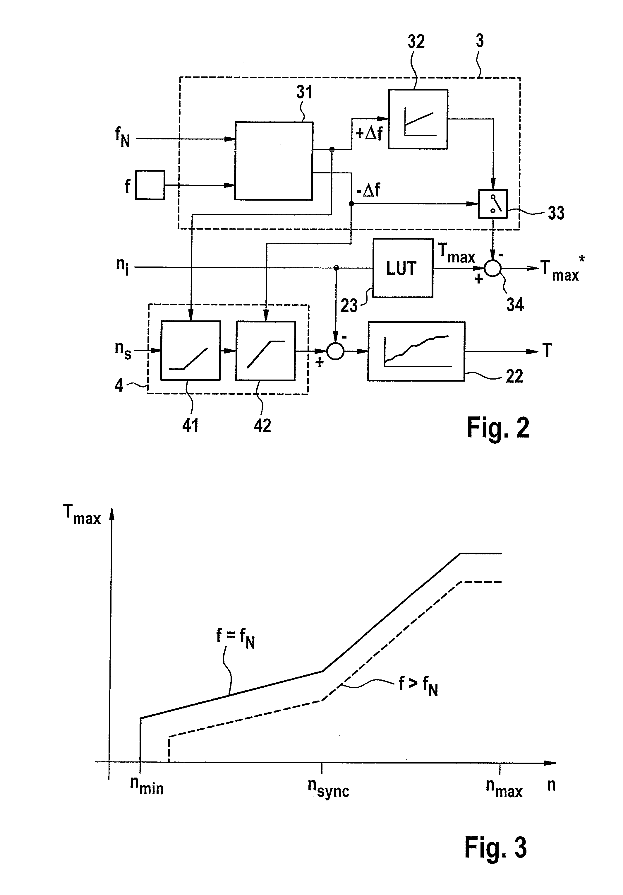
[0011]The invention is based on the idea of not adapting the operating torque over the entire operating range, but of carrying out the adaptation only with respect to the permissible limit values, in particular the maximum value, but with this adaptation not being carried out statically, but dynamically as a function of the actually occurring frequency discrepancy. This makes it possible to link the previously contradictory advantages of the previously known solution options, and therefore to reduce their respective disadvantages. In particular, dynamic limiting avoids the disadvantage of yield losses always occurring, such as those which have previously unavoidably occurred in the past when designing for the worst case. Since only the limit value and not the entire characteristic is shifted over the entire operating range, the losses can be further reduced.
[0017]It is also possible to design the rotation-speed modification element to form the modified rotation-speed signal from the real rotation-speed, using the ratio of the nominal grid frequency to the actual grid frequency, and possibly taking into account the saturation element. The rotation-speed can therefore be modified in a particularly simple and expedient manner.

Problems solved by technology

If the slip values in consequence become too high or too low, then there is a risk of overloading and of damage to components of the wind energy installation.
In the end, this leads to planned overengineering of the components, and is therefore correspondingly expensive, in terms of production costs.
Furthermore, when the characteristics are matched to the worst case, this leads to sub-optimum operation at the nominal frequency, resulting in yield losses.
In addition, this design based on the extreme case is still completely inadequate and, furthermore, the steady-state rotation-speed range must be matched to the grid frequency in order to prevent overloading in the event of excessive rotor slip, in particular in the event of a relatively heavy load, when an actual underfrequency occurs.
This has the disadvantage that this adaptation acts over the entire operating range, which can likewise result in yield losses as a result of unnecessary reduction, as already described above for the static design based on the extreme case.
Furthermore, this results only in inadequate protection for certain operating states, for example for the combination of overfrequency and high load.
Adequate protection cannot be ensured in particular for this critical operating situation.

Method used


Image

  • Wind energy installation with variable rotation speed characteristic
  • Wind energy installation with variable rotation speed characteristic
  • Wind energy installation with variable rotation speed characteristic

Examples


Embodiment Construction

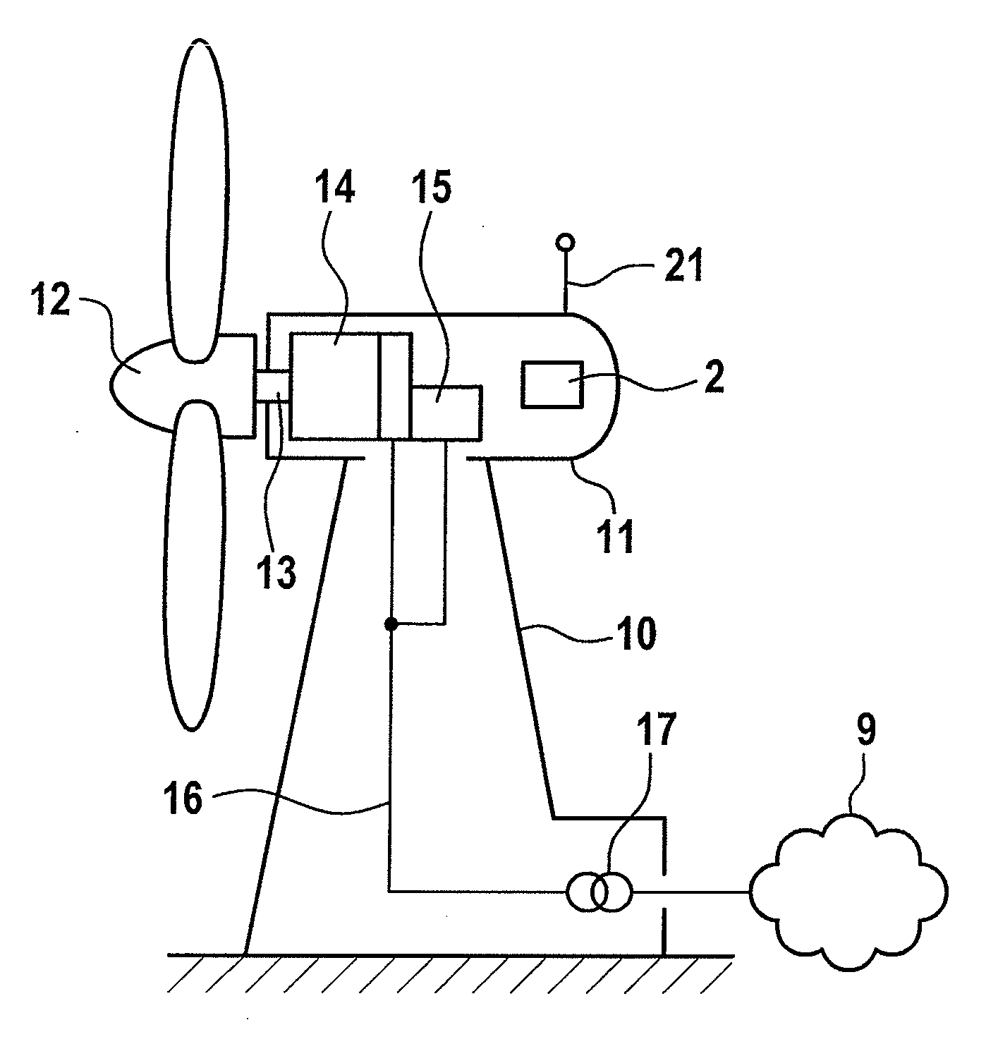
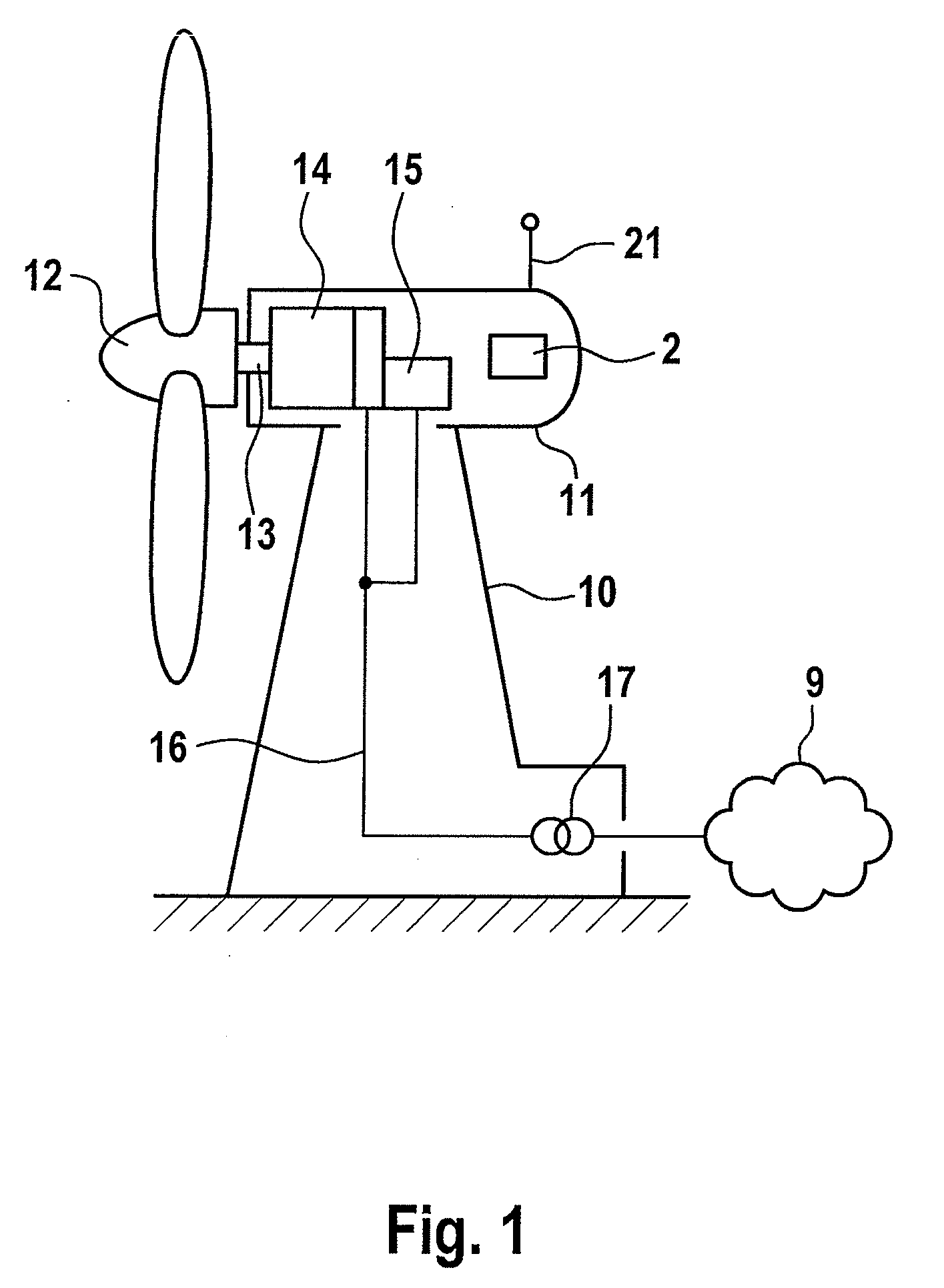
[0025]The wind energy installation has a tower 10 at whose upper end a pod 11 is arranged such that it can swivel in the azimuth direction. A wind rotor 12 is arranged, such that it can rotate, on an end face of the pod 11 and, via a rotor shaft 13, drives a generator which is designed to convert mechanical energy to electrical energy. In the illustrated exemplary embodiment, this is a doubly-fed asynchronous generator 14, which interacts with a converter 15. The electrical power produced by the generator 14 with the converter 15 is emitted via a connecting line 16 to a transformer 17, which is arranged at the foot of the tower 10 of the wind energy installation. This is connected to a distribution grid 9, which may be an internal grid for a wind farm, or a public power transmission grid.

[0026]Furthermore, a controller 2 is arranged on the pod 11, is connected via signal lines (not illustrated) to the various components of the wind energy installation, and controls them. In turn, co...


PUM


Abstract

A wind energy installation including a wind rotor, a doubly-fed asynchronous generator driven by the wind rotor, a converter, and a controller configured to determine an operating torque for an operating rotation-speed, the operating torque not exceeding a maximum torque. The installation also includes a frequency-adaptive torque limiter having a classifier—for an overfrequency or underfrequency, a torque shifter configured to reduce the maximum torque in the event of frequency discrepancies, and an inhibitor configured to block the torque shift at an underfrequency. The installation further includes a frequency-dependent rotation-speed limiter configured to interact with the classifier such that a lower limit rotation-speed is increased only at an overfrequency and an upper limit rotation-speed is reduced only at an underfrequency. Accordingly, the operating torque can be adapted with respect to the permissible limit values rather than over the entire operating range, thus minimizing yield losses when frequency discrepancies occur.

Description

REFERENCE TO RELATED APPLICATIONS[0001]This application claims the priority of German Patent Application No. 10 2009 037 238.5, filed Aug. 12, 2009, the contents of which are incorporated herein by reference.FIELD OF THE INVENTION[0002]The invention relates to a wind energy installation having a wind rotor, a doubly-fed asynchronous generator which is driven by the wind rotor and, having a converter, which comprises a generator-side inverter and a grid-side inverter, as well as a controller which is designed to determine an operating torque for an operating rotation-speed, with the operating torque not exceeding a maximum torque, and which furthermore has a grid frequency detector.BACKGROUND OF THE INVENTION[0003]Modern wind energy installations are designed for variable rotation speeds and, for this purpose, are provided with a converter. Normally, they have a doubly-fed asynchronous generator, whose stator is permanently connected to the grid, and the rotor is connected to the gri...

Claims


Application Information

Patent Timeline
Patent Type & Authority Applications(United States)
IPC IPC(8): H02P9/04
CPCF03D9/003F05B2270/1032H02J3/28H02J3/386Y02E10/763Y02E10/766Y02E70/30F03D7/0284Y02E10/723F03D9/255Y02P80/30H02J2300/28H02J3/381Y02E10/76Y02E10/72F03D7/0272
Inventor KRUEGER, THOMAS
Owner SIEMENS GAMESA RENEWABLE ENERGY SERVICE GMBH
Learn More