Eureka AIR delivers breakthrough ideas for toughest innovation challenges, trusted by R&D personnel around the world.

Switching regulator with transient control function and control circuit and method therefor

Inactive Publication Date: 2011-02-17
RICHTEK TECH
View PDF11 Cites 9 Cited by
  • Summary
  • Abstract
  • Description
  • Claims
  • Application Information

AI Technical Summary

Benefits of technology

[0014]In another perspective, the present invention provides a control circuit for a switching regulator, wherein the switching regulator receives an input voltage and generates an output voltage at an output terminal, the output terminal being coupled to an output capacitor, the control circuit comprising: an error amplifier for receiving a feedback signal representing the output voltage and comparing the feedback signal with a first reference signal; a PWM generator for generating a PWM signal according to an output of the error amplifier; a first comparator for comparing the feedback signal with a second reference signal to determine whether the output voltage is higher than a first predetermined threshold; a second comparator for comparing the feedback signal with a third reference signal to determine whether the output voltage is lower than a second predetermined threshold; a first switch coupled between the output capacitor and a voltage node having a lower voltage level than the output voltage, wherein the first switch is turned on when the output voltage is determined to be hi

Problems solved by technology

However, in either mode, when the load current changes abruptly, it will cause output voltage overshoot or undershoot, generating a larger ripple at the output terminal as shown in FIG. 7.

Method used


Image

  • Switching regulator with transient control function and control circuit and method therefor
  • Switching regulator with transient control function and control circuit and method therefor
  • Switching regulator with transient control function and control circuit and method therefor

Examples


Embodiment Construction

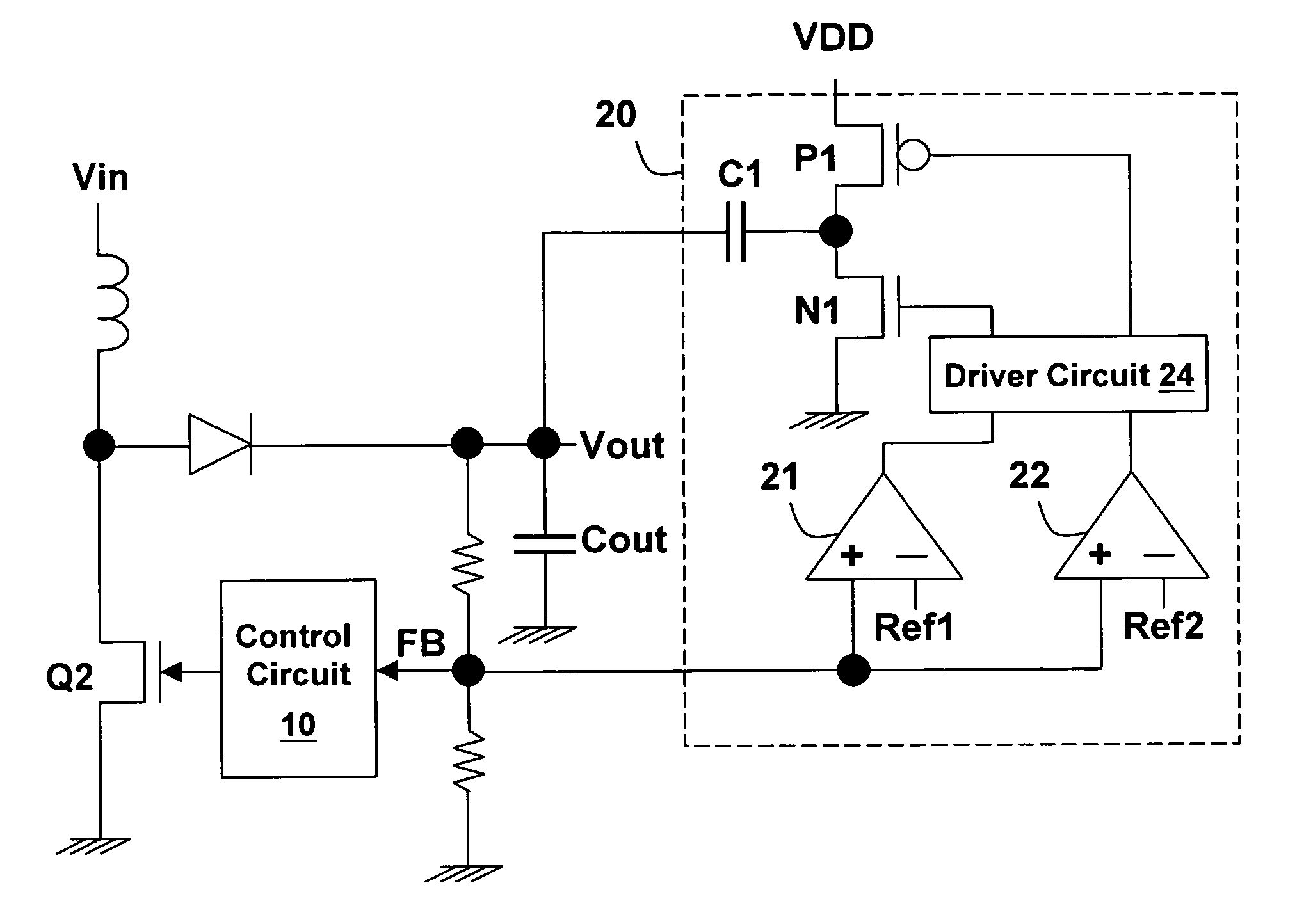
[0028]Please refer to FIG. 8, an asynchronous boost switching regulator is shown by way of example to illustrate the present invention. However, the present invention is not limited to the asynchronous boost switching regulator and can be applied similarly to other types of synchronous or asynchronous switching regulators. FIG. 8 shows the first embodiment of the present invention, wherein a voltage balancing circuit 20 is provided, in addition to the basic circuit structure of an asynchronous boost switching regulator. The voltage balancing circuit 20 can be entirely or partially integrated with a control circuit 10 to become an integrated circuit. The voltage balancing circuit 20 is provided for: (1) releasing the energy stored in an output capacitor Cout when the output voltage Vout is too high, and (2) supplying energy to the output capacitor Cout when the output voltage Vout is too low. As such, the switching regulator has a transient control function which can improve the tran...


PUM


Abstract

The present invention discloses a switching regulator with transient control function, and a control circuit and a method for controlling the switching regulator. The switching regulator with transient control function includes: a power conversion circuit for receiving an input voltage and converting the input voltage to an output voltage; a feedback circuit for detecting the output voltage and generating a feedback signal representing the output voltage; an output capacitor coupled to an output terminal of the power conversion circuit; and a control circuit for receiving the feedback signal and generating a control signal to control the conversion operation by the power conversion circuit accordingly, wherein the control circuit includes a voltage balancing circuit which discharges the output capacitor when the output voltage is higher than a first predetermined threshold, and charges the output capacitor when the output voltage is lower than a second predetermined threshold.

Description

CROSS REFERENCE[0001]The present invention claims priority to Taiwan patent application No. 098127645, filed on Aug. 17, 2009.BACKGROUND OF THE INVENTION[0002]1. Field of Invention[0003]The present invention relates to a switching regulator with transient control function and a control circuit and a method therefor.[0004]2. Description of Related Art[0005]There are various types of switching regulators, such as buck converter, boost converter, inverter converter, buck-boost converter and so on. The foregoing circuits can also be categorized into synchronous type and asynchronous type; a synchronous switching regulator employs two power transistor switches (the buck-boost converter employs four power transistor switches), while in an asynchronous switching regulator one of the power transistor switches is replaced by a diode. Taking a synchronous buck converter for example, its circuit structure is shown schematically in FIG. 1. The buck converter 1 includes two power transistor swit...

Claims


Application Information

Patent Timeline
IPC IPC(8): G05F1/10
CPCH02M3/158
Inventor LIU, KUO-CHICHAO, HENG-SHENG
Owner RICHTEK TECH
Why Eureka
Eureka Blog
Learn More