Distance measuring apparatus and distance measuring method

a distance measurement and distance measurement technology, applied in distance measurement, height/levelling measurement, instruments, etc., can solve the problems of difficult to obtain a sufficiently long base line length b, the position of the optical axes of the optical system will also change in a complicated manner, and the accuracy of distance measurement is likely to be deteriorated. , to achieve the effect of high accuracy, shortening the focus distance, and realizing the accuracy of distance measuring apparatus

Active Publication Date: 2011-02-17
PANASONIC CORP
View PDF2 Cites 16 Cited by
  • Summary
  • Abstract
  • Description
  • Claims
  • Application Information

AI Technical Summary

Benefits of technology

[0032]According to the present invention, by imaging an object for distance measurement and a reference object with different wavelengths of light, and imaging the reference object with light of a short wavelength, the focusing distance can be shortened; therefore, even if the reference object is placed at a position close to the imaging regions of the imaging elements, the reference object and the object for distance measurement can be imaged with about the same optical accuracy. This allows the reference object to be placed near the imaging sections, whereby a small-sized distance measuring apparatus can be realized.
[0033]Moreover, by using an amount of change from the initial value of a parallax amount of the reference value to correct a parallax amount of the object for distance measurement, a change in the base line length due to temperature changes, aging, and the like can be corrected. Because the object for distance measurement and the reference object are imaged with the same optical systems, the correction of a change in the base line length attains a high accuracy, whereby a highly accurate distance measuring apparatus can be realized.

Problems solved by technology

Generally speaking, in an environment where a distance measuring apparatus is used, the distance measuring apparatus itself is required to be small in size, which makes it difficult to obtain a sufficiently long base line length B. As can be seen from (eq.
However, if the parallax amount Δ is small, the accuracy of distance measurement is likely to be deteriorated due to various factors.
If the distance measuring apparatus has a complex structure, the positions of the optical axes of the optical systems will also change in a complicated manner.
It is difficult to estimate the resultant amount of change in the parallax amount Δ, and it is also difficult to correct the amount of change.
In this case, the distance measuring apparatus cannot be used other than in a temperature range where decrease in the accuracy of distance measurement is tolerated.

Method used


Image

  • Distance measuring apparatus and distance measuring method
  • Distance measuring apparatus and distance measuring method
  • Distance measuring apparatus and distance measuring method

Examples


first embodiment

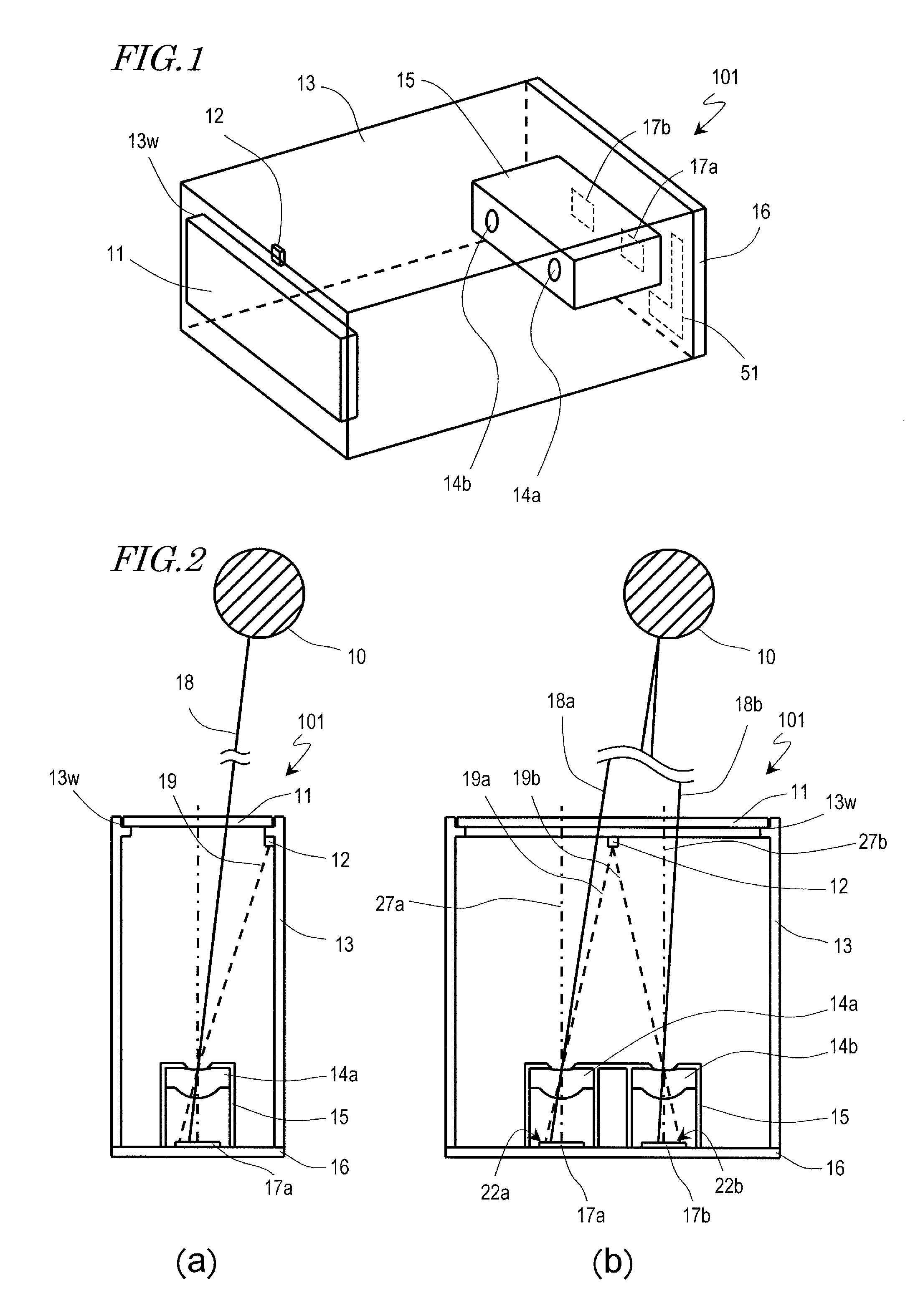
[0077]Hereinafter, a first embodiment of the distance measuring apparatus according to the present invention will be described. FIG. 1 is a perspective view of the distance measuring apparatus 101. FIGS. 2(a) and (b) are cross-sectional views of the distance measuring apparatus 101 as seen from a lateral direction and from an upper direction, respectively.

[0078]The distance measuring apparatus 101 includes an optical filter 11, a reference object 12, optical systems 14a and 14b, imaging sections 17a and 17b, and a signal processing circuit 51. It further includes a housing 13, a barrel 15, and a substrate 16 for accommodating or supporting these constituent elements.

[0079]The housing 13 has an opening 13w, such that the optical filter 11 is attached to the opening 13w. The reference object 12 is provided in the vicinity of the opening 13w, near the center of the opening 13w along the longitudinal direction thereof.

[0080]The substrate 16 is attached to a face of the housing 13 opposi...

second embodiment

[0130]Hereinafter, a second embodiment of the distance measuring apparatus according to the present invention will be described. FIG. 9 is a perspective view of a distance measuring apparatus 102. FIGS. 10(a) and (b) are cross-sectional views of the distance measuring apparatus 102 as seen from a lateral direction and from an upper direction, respectively.

[0131]The distance measuring apparatus 102 differs from the distance measuring apparatus 101 of the first embodiment in that no optical filter is provided in the opening 13w of the housing 13, and that imaging sections 17a′ and 17b′ having filter portions 65a and 65b which respectively cover the imaging regions 22a and 22b are comprised. Moreover, although the reference object 12 in the first embodiment is a light-emitting device which emits light of the first wavelength band, the distance measuring apparatus 102 includes a light-emitting device which emits white light as a reference object 12′. Moreover, the reference object 12′ i...

third embodiment

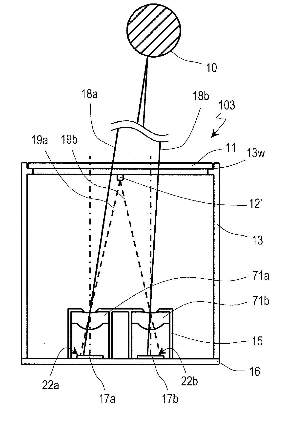
[0139]Hereinafter, a third embodiment of the distance measuring apparatus according to the present invention will be described. FIG. 12 is a cross-sectional view of a distance measuring apparatus 103 as seen from an upper direction. The distance measuring apparatus 103 of the present embodiment differs from the distance measuring apparatus 101 of the first embodiment in that optical systems 71a and 71b composed of diffractive lenses having a diffraction grating on at least one face thereof are comprised, instead of the optical systems 14a and 14b in the distance measuring apparatus 101 of the first embodiment.

[0140]The optical systems 71a and 71b of the present embodiment have sawtooth diffraction gratings exhibiting a high diffraction efficiency with respect to a specific order and wavelength, called blazed diffraction gratings. FIG. 13 shows a cross-sectional structure of the optical systems 71a and 71b, and as shown in FIG. 13, a blazed diffraction grating is formed on one surfac...


PUM


Abstract

A distance measuring apparatus according to the present invention for measuring a distance to an object based on a parallax of images obtained with a plurality of optical systems includes: a reference object (12); a plurality of optical systems (14a, 14b); imaging sections (17a, 17b) for converting images of the object for distance measurement and the reference object formed in the respective imaging regions by the plurality of optical systems into electrical signals; and a calculation section. From the electrical signals, the calculation section generates a plurality of picture data of the reference object by light of a first wavelength band of the reference object in the plurality of imaging regions and a plurality of picture data of the object for distance measurement by light of a second wavelength band of the object for distance measurement in the plurality of imaging regions, the second wavelength band being longer in wavelength than is the first wavelength band. From the plurality of picture data of the reference object and the plurality of picture data of the object for distance measurement, parallax amounts of the reference object and the object for distance measurement are calculated, and based on the parallax amount of the reference object and an initial value of the parallax amount of the reference object, the parallax amount of the object for distance measurement is corrected, and a distance to the object for distance measurement is calculated based on the corrected parallax amount of the object for distance measurement.

Description

TECHNICAL FIELD[0001]The present invention relates to a distance measuring apparatus for measuring a distance to an object by using triangulation, and in particular to a distance measuring apparatus and distance measuring method incurring few errors.BACKGROUND ART[0002]A distance measuring apparatus which measures a distance to an object by using triangulation usually comprises a pair of optical systems and imaging elements. For example, the pair of optical systems are disposed along the horizontal (right-left) direction or the vertical (up-down) direction, and images from light of the object respectively converged by the pair of optical systems are converted into electrical signal-based pictures by the imaging elements. This is called imaging. Moreover, in the present specification, a picture is meant to be an image containing an object as electrically converted by an imaging element. A distance measuring apparatus determines a parallax amount between two pictures that have been im...

Claims


Application Information

Patent Timeline
Patent Type & Authority Applications(United States)
IPC IPC(8): G01C3/08
CPCG01C3/24
Inventor IMAMURA, NORIHIRO
Owner PANASONIC CORP
Why Eureka
Try Eureka