Ramp for a hard disc drive

Inactive Publication Date: 2011-02-17
SAE MAGNETICS (HK) LTD
View PDF14 Cites 16 Cited by
  • Summary
  • Abstract
  • Description
  • Claims
  • Application Information

AI Technical Summary

Benefits of technology

[0010]An object of the present invention is to provide an improved ramp device for parking read/write heads in hard disc drives. The improvement permitting loading the heads from the front side of the ramp thereby reducing head travel during loading while yielding more space on the coil side to provide more room for a more efficient voice coil motor. Moreover,

Problems solved by technology

For the past several years, data storage methods have followed a tendency of escalating storage capacity while also shrinking the physical size occupied b

Method used


Image

  • Ramp for a hard disc drive
  • Ramp for a hard disc drive
  • Ramp for a hard disc drive

Examples


Embodiment Construction

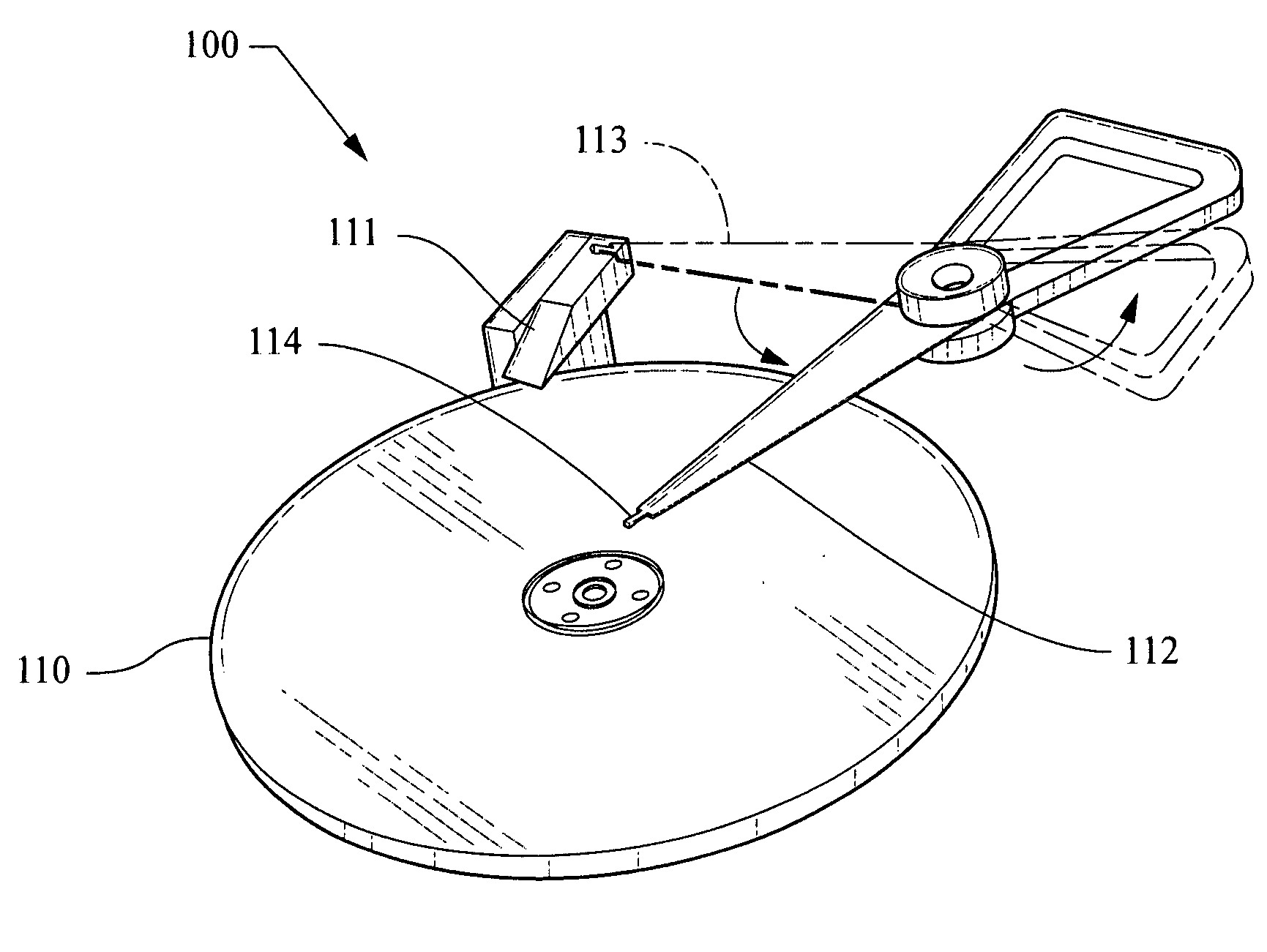
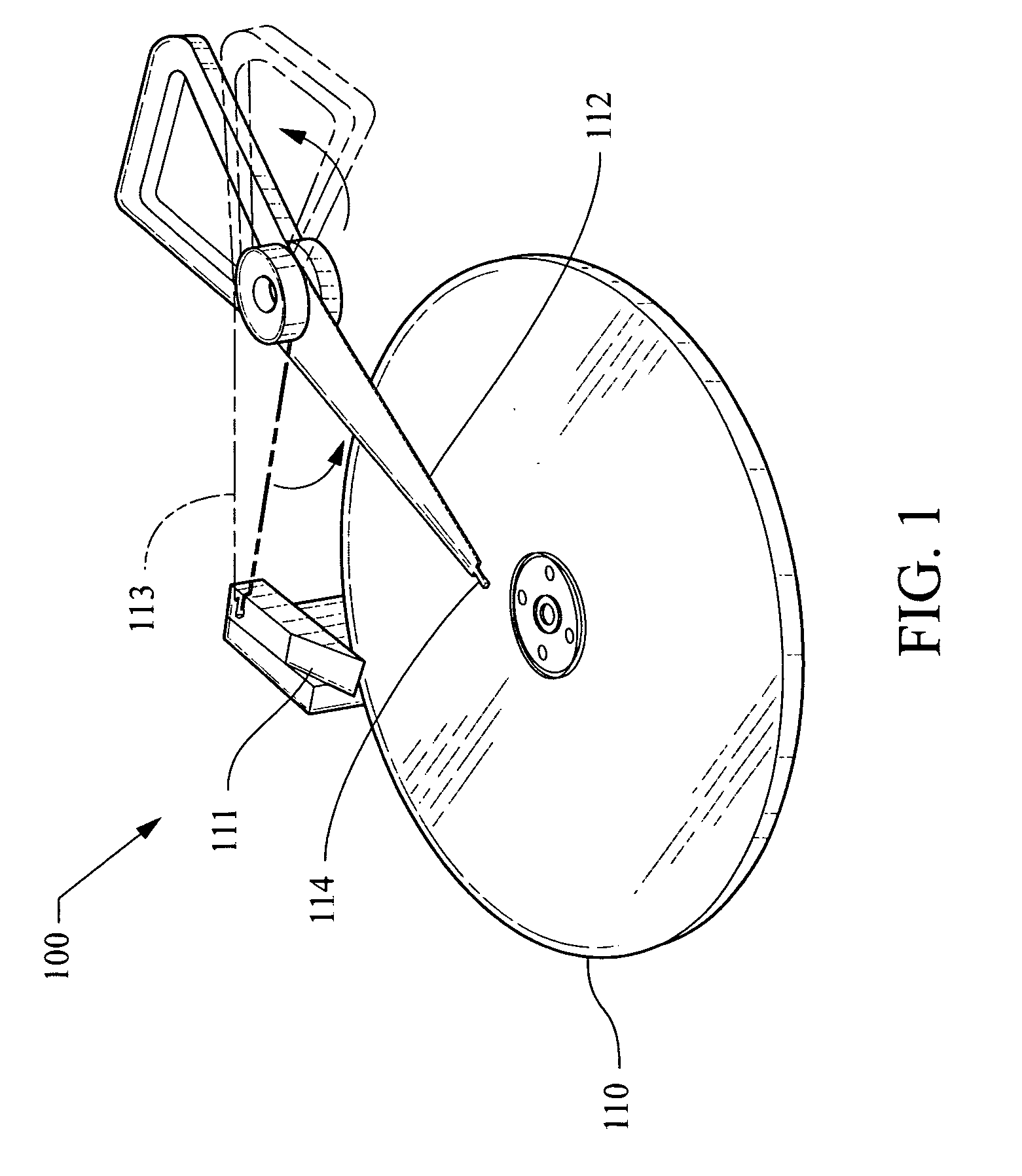
[0028]FIG. 1 illustrates a schematic of a ramp 111 for a hard disk drive 100, of the prior art, with a suspension head slider in a park position 113. The suspension head rotates into a read / write mode 112 as the rotating disc 110 provides an air bearing effect as the read / write head slider 114 floats over the disc surface.

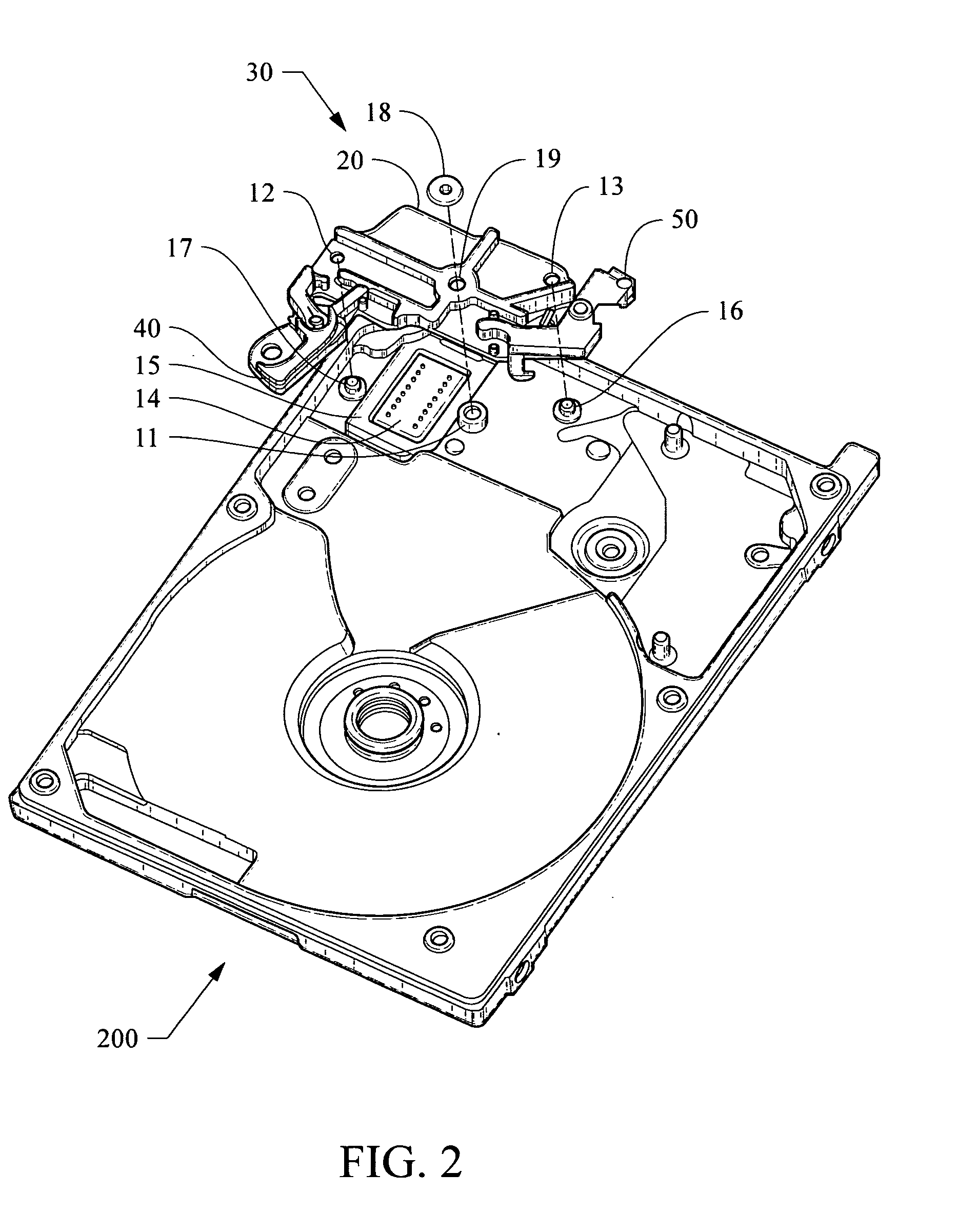
[0029]FIG. 2 illustrates a perspective top view of a hard disk drive 200 showing the top surface of a connector bracket assembly 30. The assembly includes a demountable ramp device 40 and a demountable latch member 50, of the invention. Assembly 30 is shown raised for clarity. The connector bracket 20 includes two alignment holes 12, 13 extending from the top to its bottom surface. The two alignment holes are positioned to fit over two locating pins 16, 17, protruding up from the base of the hard disk drive 200. The locating pins are used to position the bracket assembly 30 to compress gasket 15. The gasket surrounds connector 14. A flexible printed circuit (not sh...


PUM


Abstract

A moveable ramp arrangement having a traditional front side while the back side has an extended rotational park position used to support the read/write heads while the ramp is in the open position before and during disc installation.

Description

BACKGROUND OF THE INVENTION[0001](1) Technical Field[0002]The present invention relates generally to hard disc drives (HDD), and more particularly to improving ramp load / unload apparatus involving a mechanism for safely positioning read / write heads.[0003](2) Description of the Prior Art[0004]Present-day mass produced hard disc drives consists of a metallic housing in which is contained one or more discs (platters) mounted on a spindle that allows the discs to rotate. The discs are made from a solid, non-magnetic material, normally aluminum or glass. The discs are coated, on each side, with a very thin layer of magnetic material into which information is stored in binary form. For both sides of each disc there is a read / write head mounted on a suspension arm that moves across the surfaces of each disc.[0005]Typically, HDDs employ a rotary actuator structure to position the suspension arm(s) transducer heads relative to recording surfaces of rotating discs. The discs are spun at high ...

Claims


Application Information

Patent Timeline
IPC IPC(8): G11B21/02
CPCG11B21/22
Inventor VISKOCHIL, STEPHEN RALPHSEYMOUR, MARK SPENCER
Owner SAE MAGNETICS (HK) LTD
Why Eureka
Try Eureka