Method for determining fluid control events in a borehole using a dynamic annular pressure control system

a control system and annular pressure technology, applied in the field of drilling boreholes, can solve the problems of drilling fluid loss, fluid entering the formation pores, and creating fissures or fractures in the formation

Inactive Publication Date: 2011-02-24
SMITH INT INC
View PDF8 Cites 45 Cited by
  • Summary
  • Abstract
  • Description
  • Claims
  • Application Information

AI Technical Summary

Benefits of technology

[0018]A method for determining existence of a well control event by controlling formation pressure during the drilling of a borehole through a subterranean formation according to another aspect of the invention includes pumping a drilling fluid through a drill string extended into a borehole, out a drill bit at the bottom end of the drill string, and into an annular space between drill string and the borehole. Pressure of the fluid pumped into the drill string is measured. The drilling fluid is discharged from the annular space proximate the Earth's surface. Existence of a well control event is determined when at least one of the following events occurs: the pumped fluid pressure remains substantially constant and pressure in the outlet of the annular space increases, and the pumped fluid pressure remains substantially constant and the pressure in the outlet of the annular space decreases.

Problems solved by technology

The fact that the drilling fluid hydrostatic pressure typically exceeds the formation fluid pressure also results in the fluid entering into the formation pores, or “invading” the formation.
Overbalanced drilling relies primarily on the hydrostatic pressure generated by the column of drilling fluid in the annular space (“annulus”) to restrain entry of formation fluids into the borehole.
However, the addition of density increasing (“weighting”) additives to the drilling fluid: (a) may not be rapid enough to deal with the formation fluid influx; and (b) may cause the hydrostatic pressure in the annulus to exceed the formation fracture pressure, resulting in the creation of fissures or fractures in the formation.
Creation of fractures or fissures in the formation typically results in drilling fluid loss to the formation, possibly adversely affecting near-borehole permeability of hydrocarbon-bearing formations.
The use of overbalanced drilling also affects the depths at which casing must be set during drilling operations.
Borehole fluid pressures in excess of the formation fracture pressure can result in the drilling fluid pressurizing the formation walls to the extent that small cracks or fractures will open in the borehole wall.
Further, the drilling fluid pressure overcomes the formation pressure and causes significant fluid invasion.
Fluid invasion can result in, among other problems. reduced permeability, adversely affecting formation production.
As noted above, while additional weighting material may be added to the drilling fluid to increase its hydrostatic pressure, such will be generally ineffective in dealing with a gas kick due to the time required to increase the fluid density at the kick depth in the borehole.
The displacement of drilling fluid results in reduction of hydrostatic pressure on the annulus, further exacerbating the gas expansion in a dangerous cycle.

Method used


Image

  • Method for determining fluid control events in a borehole using a dynamic annular pressure control system
  • Method for determining fluid control events in a borehole using a dynamic annular pressure control system
  • Method for determining fluid control events in a borehole using a dynamic annular pressure control system

Examples


Embodiment Construction

1. Drilling Circulation System and First Embodiment of a Backpressure Control System

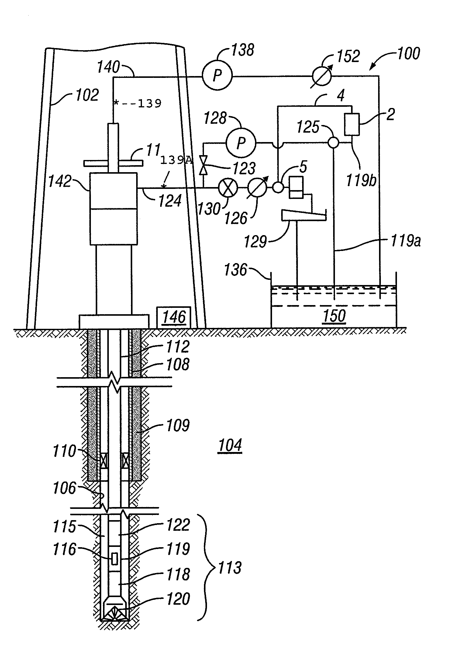
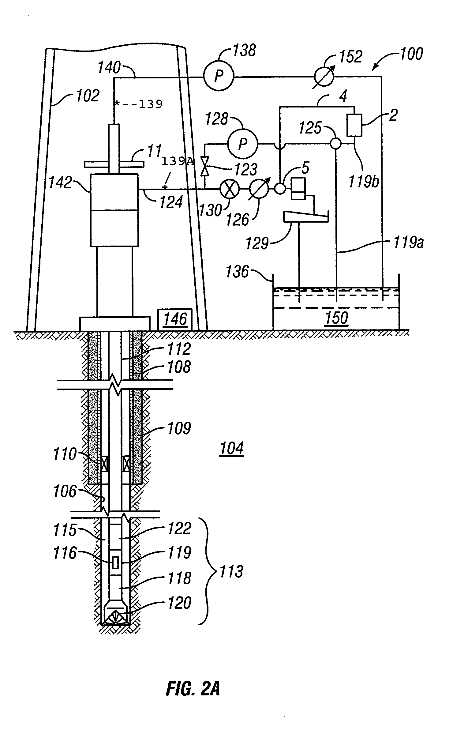
[0031]FIG. 2A is a plan view depicting a land-based drilling system having one embodiment of a dynamic annular pressure control (DAPC) system that can be used with the invention. It will be appreciated that an offshore drilling system may likewise have a DAPC system using methods according to the invention. The drilling system 100 is shown including a drilling rig 102 that is used to support drilling operations. Many of the components used on the drilling rig 102, such as the kelly, power tongs, slips, draw works and other equipment are not shown separately in the Figures for clarity of the illustration. The rig 102 is used to support a drill string 112 used for drilling a borehole through Earth formations such as shown as formation 104. As shown in FIG. 2A the borehole 106 has already been partially drilled, and a protective pipe or casing 108 set and cemented 109 into place in part of the drilled p...


PUM


Abstract

A method for determining existence of a borehole fluid control event by controlling formation pressure during the drilling of a borehole includes selectively pumping a drilling fluid through a drill string extended into a borehole, out a drill bit at the bottom end of the drill string, and into an annular space between drill string and the borehole. The drilling fluid leaves the annular space proximate the surface. Existence of a well control event is determined when at least one of the following events occurs: the rate of the selective pumping remains substantially constant and the annular space pressure increases, and the rate of the selective pumping remains substantially constant and the annular space pressure decreases.

Description

CROSS-REFERENCE TO RELATED APPLICATIONS[0001]Priority is claimed from U.S. Provisional Application No. 61 / 235,152 filed on Aug. 19, 2009.STATEMENT REGARDING FEDERALLY SPONSORED RESEARCH OR DEVELOPMENT[0002]Not applicable.BACKGROUND OF THE INVENTION[0003]1. Field of the Invention[0004]The invention relates generally to the field of drilling boreholes through subsurface rock formations. More specifically, the invention relates to methods for determining borehole fluid control events, such as loss of drilling fluid or formation fluid entry into a borehole.[0005]2. Background Art[0006]The exploration for and production of hydrocarbons from subsurface Earth formations ultimately requires a method to reach and extract the hydrocarbons from the formations. The reaching and extracting are typically performed by drilling a borehole from the Earth's surface to the hydrocarbon-bearing Earth formations using a drilling rig. In its simplest form, a land-based drilling rig is used to support a dr...

Claims


Application Information

Patent Timeline
Patent Type & Authority Applications(United States)
IPC IPC(8): E21B47/00
CPCE21B21/08
Inventor REITSMA, DONALD G.
Owner SMITH INT INC
Why Eureka
Try Eureka