
Method of improving waterflood performance using barrier fractures and inflow control devices

a technology of inflow control device and waterflood performance, which is applied in the direction of drinking water installation, borehole/well accessories, construction, etc., can solve the problem of insufficient production through inflow control device, and achieve the effect of reducing the influx of injected fluid and increasing sweep efficiency

Active Publication Date: 2011-02-24
HALLIBURTON ENERGY SERVICES INC
View PDF30 Cites 38 Cited by
  • Summary
  • Abstract
  • Description
  • Claims
  • Application Information

AI Technical Summary

Benefits of technology

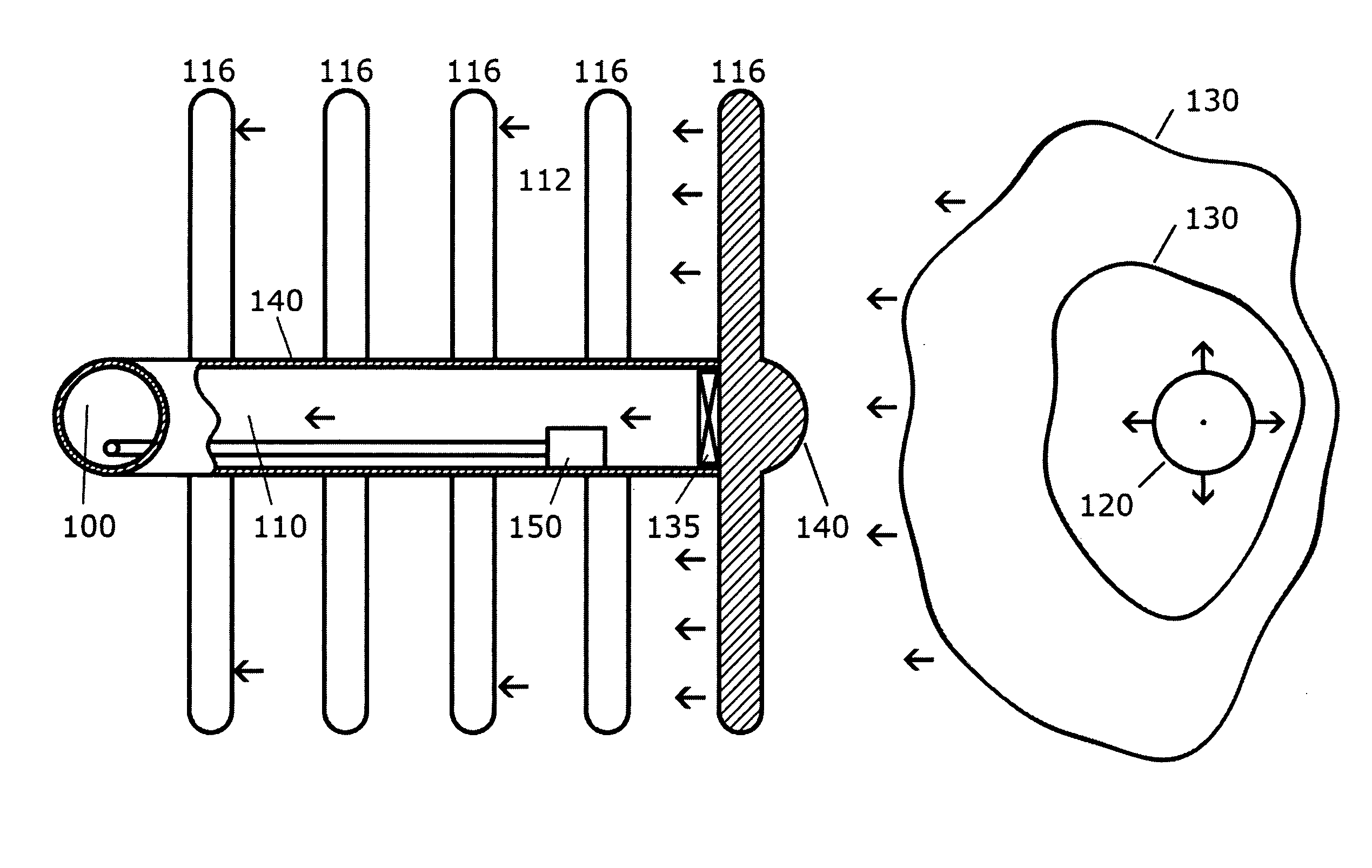
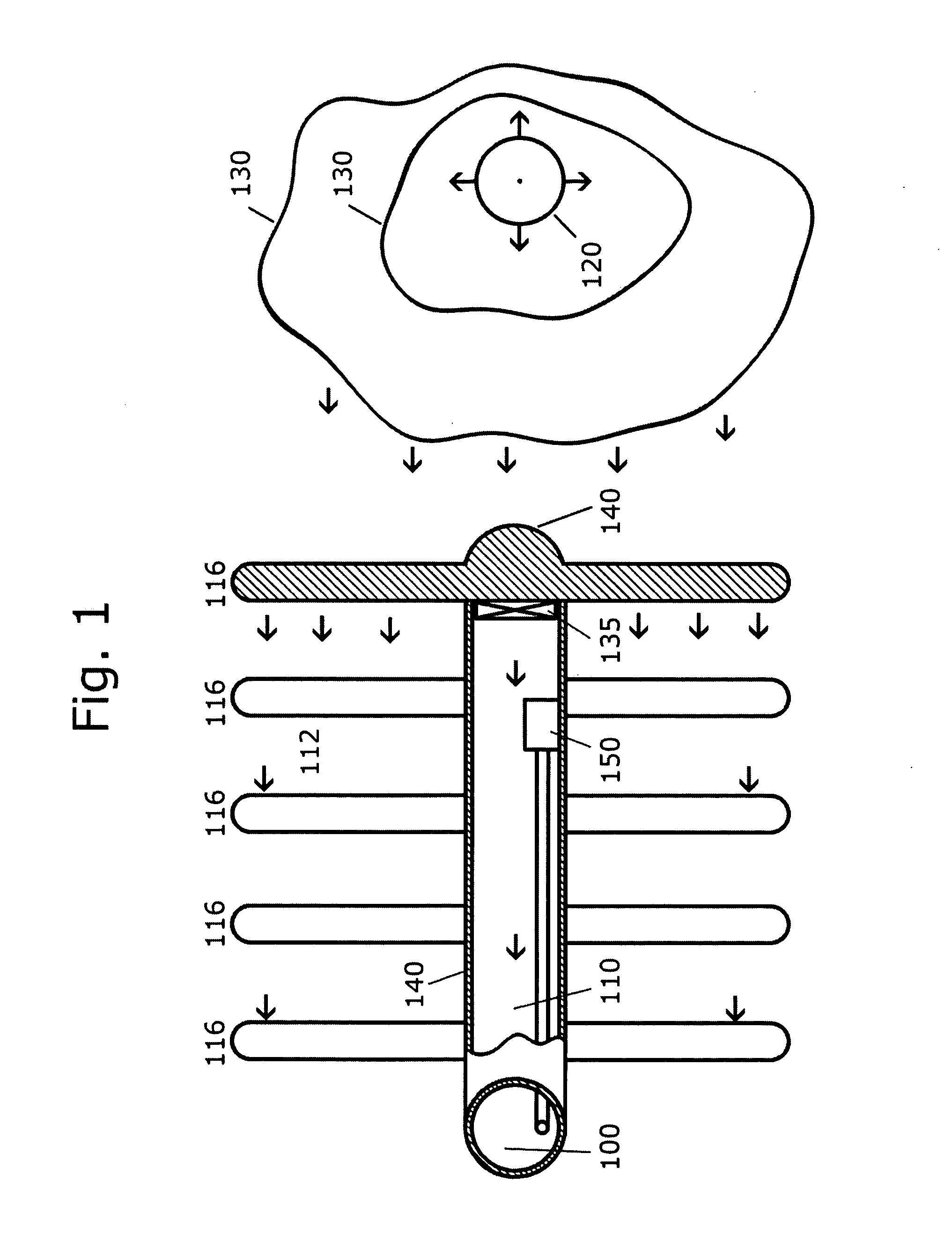
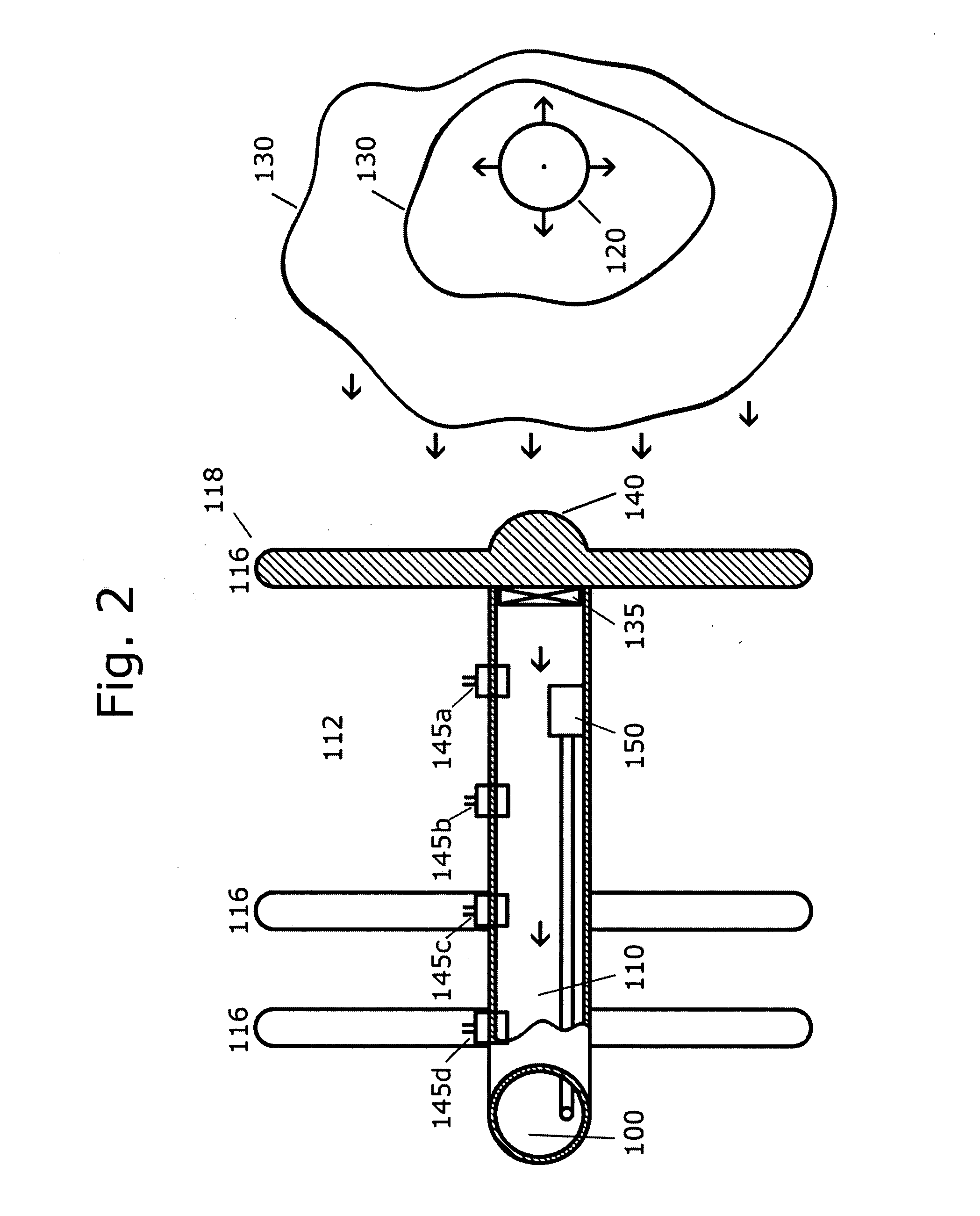
The present invention provides a method for hydrocarbon production from a reservoir using a horizontal wellbore with non-conductive fractures. The non-conductive fractures act as a barrier to divert non-hydrocarbon fluids away from the production intervals. The method includes injecting fluid into the reservoir through an injection well and using inflow control devices to distribute the fluid pressure optimally along the horizontal wellbore. The inflow control devices can be selectively closed or sealed when production reaches an unacceptable level of non-hydrocarbon fluids. The design of the hydrocarbon production system includes determining the stress field within the reservoir, designing at least one horizontal well in the direction of the minimum horizontal stress, and designing a plurality of fractures transverse to the wellbore. The design parameters are varied to optimize the hydrocarbon production system design for the reservoir.

Problems solved by technology

The method can further comprise the selective closing or sealing of an inflow control device when production through the inflow control device reaches an unacceptable level of non-hydrocarbon fluids with the hydrocarbon production.
Additional inflow control devices can be selectively closed or sealed when production from the production interval associated with such inflow control devices reach an unacceptable level of non-hydrocarbon fluids with the hydrocarbon production.

Method used


Image

  • Method of improving waterflood performance using barrier fractures and inflow control devices
  • Method of improving waterflood performance using barrier fractures and inflow control devices
  • Method of improving waterflood performance using barrier fractures and inflow control devices

Examples


examples

Reservoir Simulation

Single Horizontal Well with Vertical Well Injector

[0066]To study the effects of the aspects of the present invention a relatively simple, homogeneous reservoir was modeled for a pressure maintenance scenario in a water flood project using numerical simulation. Table 1 shows the reservoir properties modeled for Scenarios 1-6. The reservoir simulator chosen is capable of incorporating reservoir heterogeneity such as high permeability streaks, faults, dipping reservoirs, etc., and fluid properties that include high mobility ratios such as those presented by heavy oil reservoirs. FIG. 5 illustrates the well layout in map form, the map size is 1 mile by 1 mile and the boundary conditions were set as no-flow boundaries.

TABLE 1Reservoir Properties Modeled - Scenarios 1 through 6PropertiesReservoir FluidBlack OilWaterMobileOil API gravity40Gas-Oil Ratio700scf / bblWater s.g.1.0Gas s.g. (air = 1.0)0.7Irreducible Water Sat.0.2Residual Oil Sat.0.1Vertical Well TVD8080Injector...


PUM


Abstract

The present invention is directed to a method of hydrocarbon production from a hydrocarbon reservoir. The method includes providing a substantially horizontal wellbore having at least one productive interval within a hydrocarbon reservoir and forming at least one non-conductive transverse fracture in the reservoir along the substantially horizontal wellbore. An injection well is also provided. A fluid is injected into the reservoir through the injection well to displace hydrocarbons within the reservoir toward a production portion of the substantially horizontal wellbore. Hydrocarbons are drained from the reservoir into at least one production interval of the substantially horizontal wellbore. Fluid production from the at least one production interval into the substantially horizontal wellbore flows through an inflow control device that can restrict the fluid flow. A non-conductive transverse fracture can form a barrier within the reservoir to divert injected fluids to increase sweep efficiency and reduce the influx of injected fluids into the production interval.

Description

FIELD OF THE INVENTION[0001]The present invention relates generally to hydrocarbon production, and more particularly to a method of increasing hydrocarbon recovery from a reservoir.BACKGROUND OF THE INVENTION[0002]In certain subterranean formations, fluid is injected into the reservoir to displace or sweep the hydrocarbons out of the reservoir. This method of production is generally referred to as a method of “Enhanced Oil Recovery” which may be water-flooding, gas injection, steam injection, etc. For the purpose of this specification, the general process will be defined as injecting a fluid (gas or liquid) into a reservoir in order to displace the existing hydrocarbons into a producing well. The primary issue with injecting fluid to enhance oil recovery is how to sweep the reservoir of the hydrocarbon in the most efficient manner possible. Because of geological differences in a reservoir, the permeability may not be homogenous. Because of such permeability differences between the v...

Claims


Application Information

Patent Timeline
Patent Type & Authority Applications(United States)
IPC IPC(8): E21B43/26E21B34/00
CPCE21B43/12E21B43/305E21B43/16
Inventor SIERRA, LEOPOLDOEAST, JR., LOYD E.SOLIMAN, MOHAMED Y.
Owner HALLIBURTON ENERGY SERVICES INC
Learn More