
Combination shelf structure

a combination shelf and structure technology, applied in the field of combination shelf structure, can solve the problems of insufficient structural strength or failure to support a heavy weight, limited application of the shelf, difficult to maintain a secured connection, etc., to enhance the strength of carrying a weight, and enhance the overall applicability of the combination shelf

Inactive Publication Date: 2011-02-24
CHENG YANG CHIANG +1
View PDF25 Cites 30 Cited by
  • Summary
  • Abstract
  • Description
  • Claims
  • Application Information

AI Technical Summary

Benefits of technology

[0007]Therefore, it is a primary objective of the present invention to provide a combination shelf that embeds the storage partition layers with the support rods to achieve a secured connection and prevent the storage partition layers and the Support rods from being loosened and shaken, so as to enhance the applicability of the combination shelf.
[0008]Another objective of the present invention is to provide a structural design for achieving a secured connection between a storage partition layer and a support rod to enhance the strength of carrying a weight for storing heavy objects and improving the overall applicability of the combination shelf.
[0009]A further objective of the present invention is to provide a structural design capable of installing an additional auxiliary support frame at a predetermine position of the storage partition layer to enhance the strength of carrying a weight, if needed, and store objects on the shelf in a more flexible and practical way.
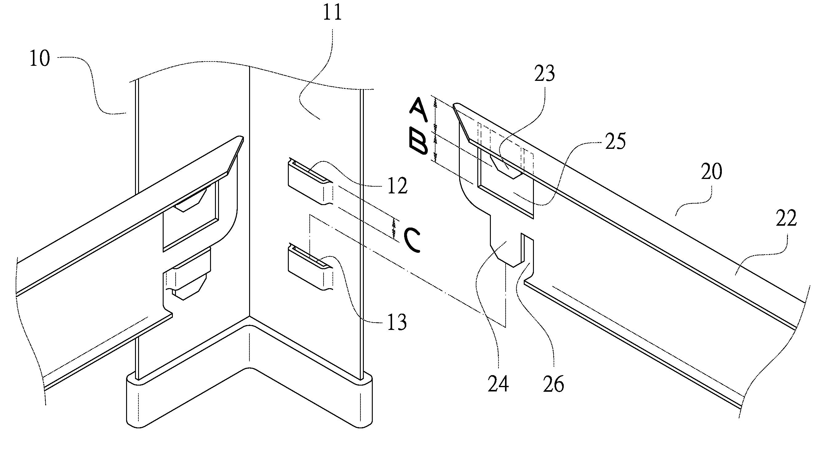
[0010]To achieve the foregoing objectives, the structural design of the present invention comprises a support rod installed at a right angle, and two support rods are installed into two upper and lower insert slots with an interval apart from one another. Upper and lower embedding plates are formed on both sides of each corner position of a frame of the storage partition layer respectively by a hollow stamping process, such that the embedding plate and the frame are situated on the same plane, and the storage partition layer can be combined securely and easily by using the embedding plate of the frame and the insert slot of the support rod. In addition, the storage partitions and the insert slots of the support rod can be rearranged with appropriate installation elements to achieve a different shape of the shelf and provide a more flexible and diversified application of the shelf.

Problems solved by technology

However, the way of connecting the support rods and the storage partition layers of the aforementioned combination shelf still has the following drawbacks.
If the support rods and the storage partition layers are connected directly by bolts, then the weight of stored objects is concentrated at locking positions of the bolts to result in an insufficient structural strength or fail to support a heavy weight, and thus the application of the shelf is limited.
If a support element is used for latching and positioning the storage partition layer, then it is difficult to maintain a secured connection between the storage partition layer and the support rod, and both of them may be shaken or loosened easily, and thus such arrangement affects the overall applicability.

Method used


Image

  • Combination shelf structure
  • Combination shelf structure
  • Combination shelf structure

Examples


Embodiment Construction

[0021]The structure, assembly technical characteristics and effects of the present invention will become apparent with the detailed description of preferred embodiment together with related drawings as follows:

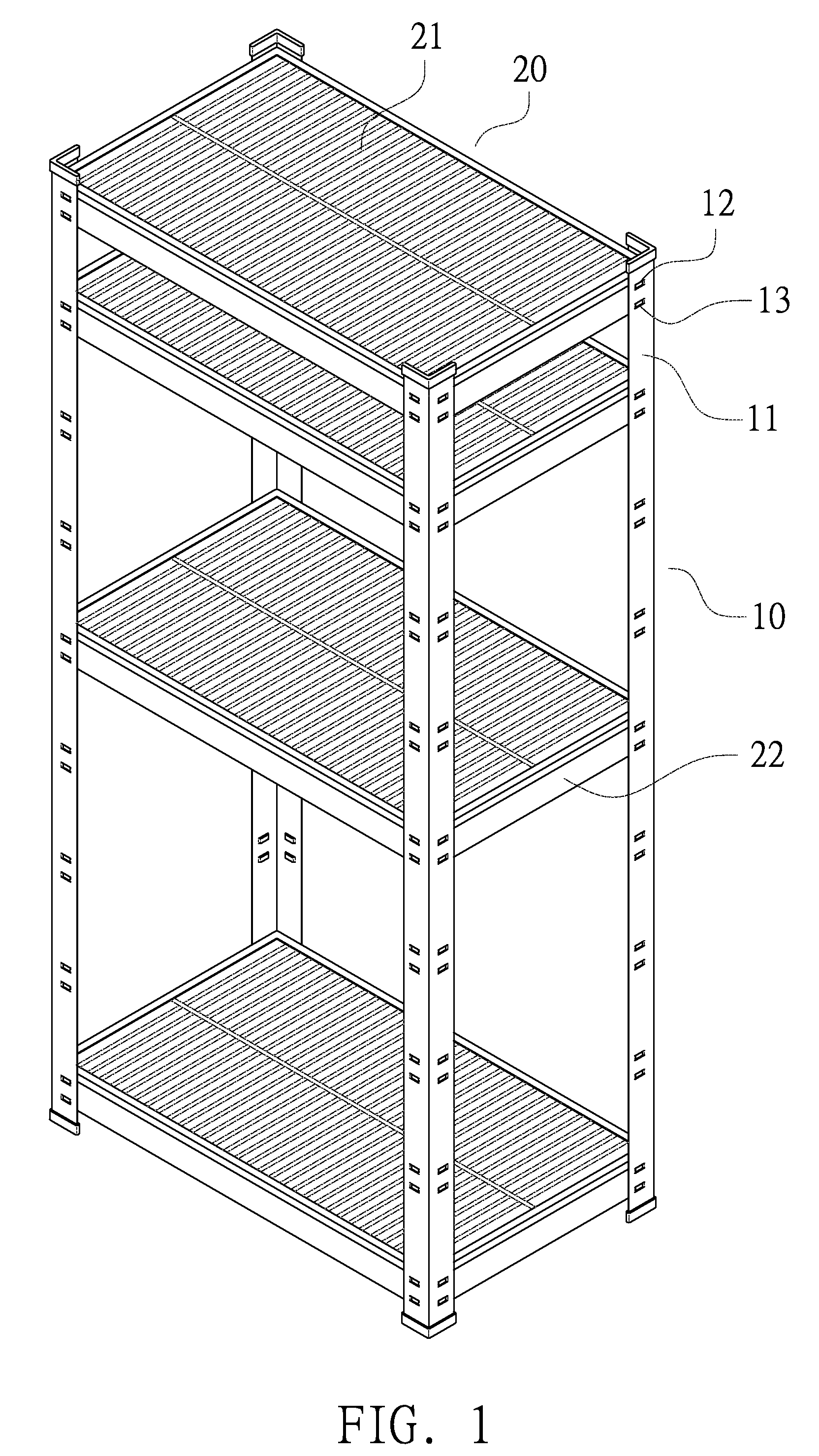
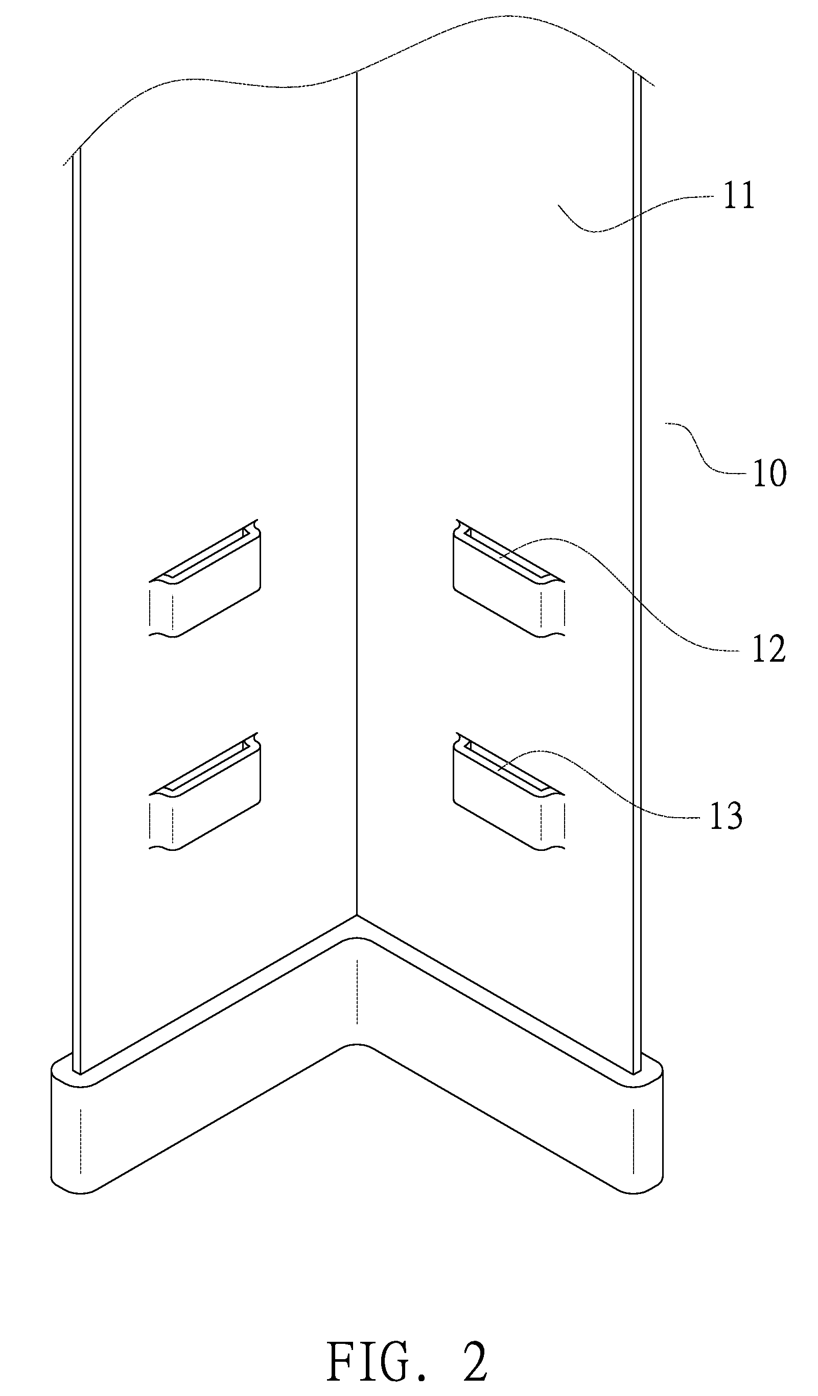
[0022]With reference to FIGS. 1 to 6 for a first preferred embodiment of the present invention, FIG. 1 shows a perspective view of a combination shelf structure. FIGS. 2 and 3 show schematic views of a portion of a combination shelf structure, FIG. 4 shows an exploded view of a portion of a combination shelf structure, FIG. 5 shows a schematic view of the connection of a combination shelf, and FIG. 6 shows a schematic view of an application of a combination shelf. The structural design of the combination shelf in accordance with the first preferred embodiment of the invention comprises four support rods 10 and a predetermined number of storage partition layers 20 embedded with each other.

[0023]The plurality of support rods10 are L-shaped plate-rods formed by stamping a metal s...


PUM


Abstract

A combination shelf structure has a design of combining storage partition layers and support rods of a combination shelf. The support rods are installed at a right angle with the storage partition layers, and two support rods are installed into two upper and lower insert slots with an interval apart from one another. Upper and lower embedding plates are formed on both sides of each corner position of a frame of the storage partition layer respectively by a hollow stamping process, such that the embedding plate and the frame are situated on the same plane, and the storage partition layer can be combined securely and easily by using the embedding plate of the frame and the insert slot of the support rod. In addition, the storage partitions and the insert slots of the support rod can be rearranged with appropriate installation elements to achieve a different shape of the shelf.

Description

BACKGROUND OF THE INVENTION[0001]1. Field of the Invention[0002]The present invention relates to a combination shelf structure, in particular to a design of a combination shelf structure that combines storage partition layers with support rods, and uses an embedding plate installed at each corner position of a frame of the storage partition layer together with an insert slot formed at a position corresponding to the support rod to embed and fix the storage partition layers with the support rods securely.[0003]2. Description of the Related Art[0004]In general, a combination shelf usually comes with a structural design comprising a plurality of support rods and a predetermined number of storage partition layers. To combine the storage partition layers with the support rods bolt holes are formed at predetermined positions of the support rods, such that bolts can be used for securing the storage partition layers, or support elements for latching and positioning the storage partition lay...

Claims


Application Information

Patent Timeline
Patent Type & Authority Applications(United States)
IPC IPC(8): A47F5/00
CPCA47B57/40A47B96/02A47B57/482
Inventor CHENG, YANG-CHIANGCHENG, SHEN-JUNG
Owner CHENG YANG CHIANG
Learn More