Remote control device and television receiver

a remote control device and receiver technology, applied in the field of remote control devices and television broadcast receivers, can solve the problems of user unaware that the heating time or thawing time has passed, and achieve the effect of effectively recognizing the elapsed tim

Inactive Publication Date: 2011-02-24
SHARP KK
View PDF1 Cites 22 Cited by
  • Summary
  • Abstract
  • Description
  • Claims
  • Application Information

AI Technical Summary

Benefits of technology

[0031]According to the present invention, it is possible to for a user to effectively recognize the elapse of a time per

Problems solved by technology

In this situation, there may be a case where the user is so preoccupied with a TV program that he or she misses an alarm sound indicating the end of the heating time.
Also in this situatio

Method used


Image

  • Remote control device and television receiver
  • Remote control device and television receiver
  • Remote control device and television receiver

Examples


first embodiment

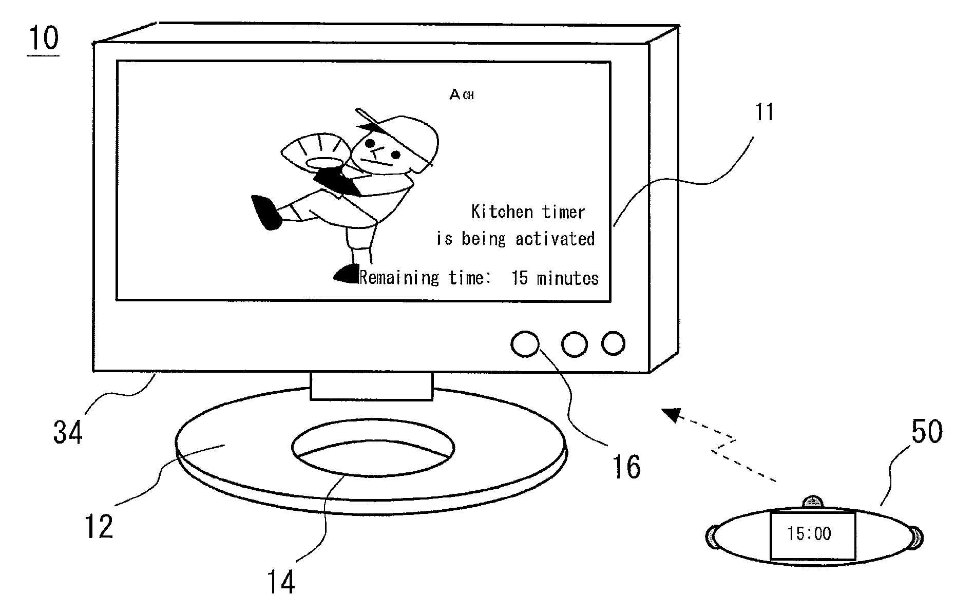
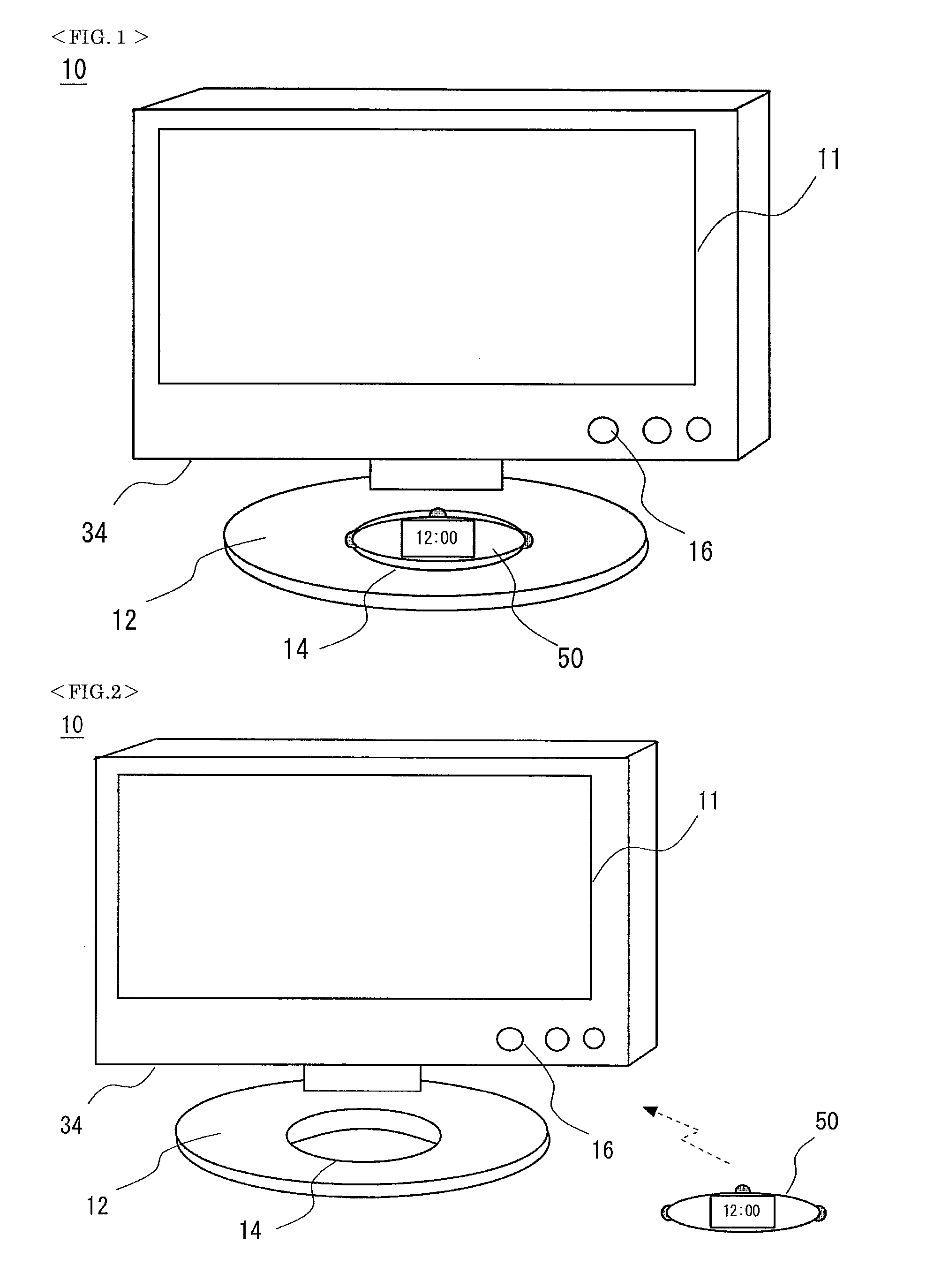
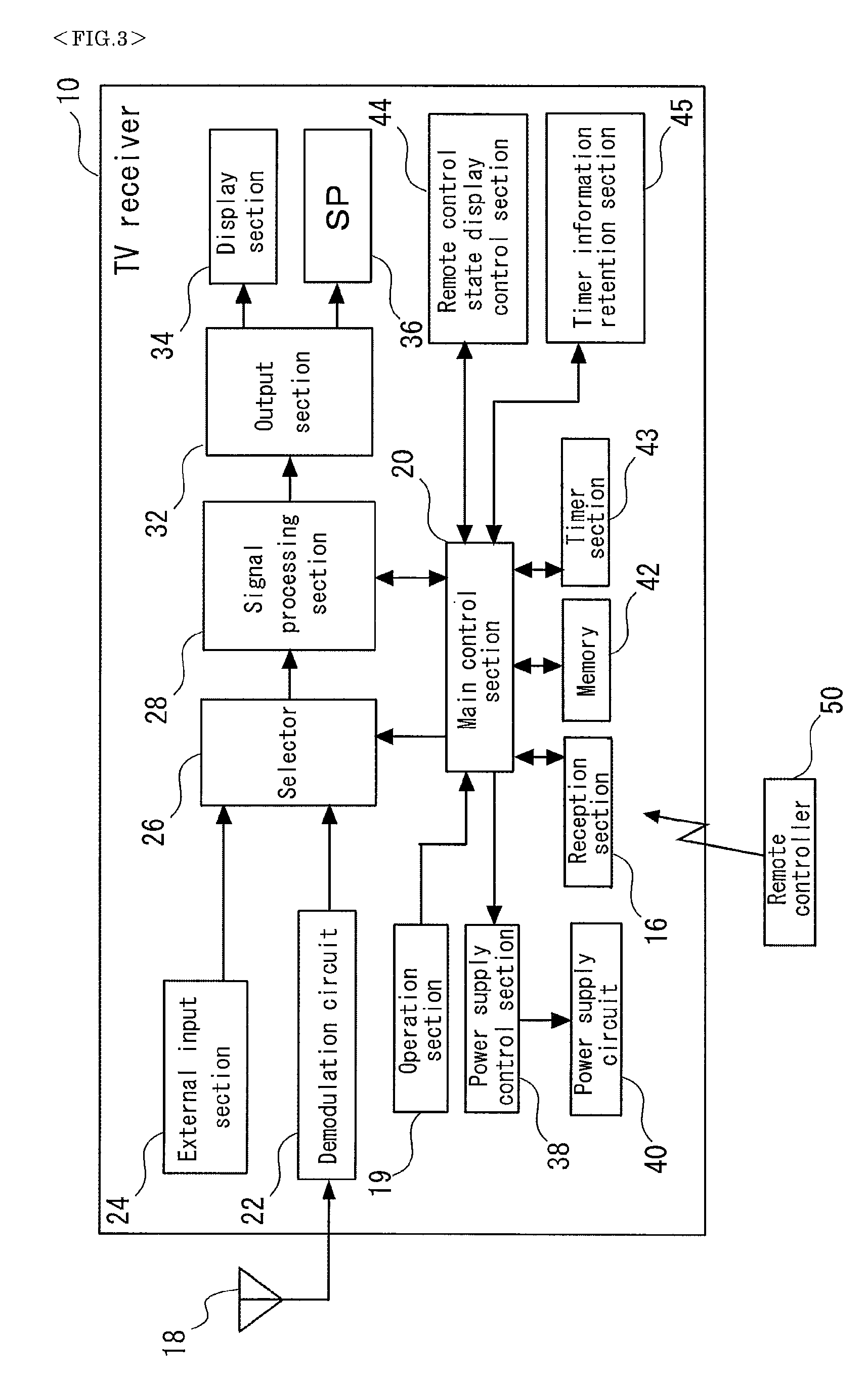
[0106]FIG. 1 is a view schematically showing the outer shape of a TV receiver 10 in a state where a substantially elliptical shaped remote controller 50 having a timer function is housed in the TV receiver 10. FIG. 2 is a view schematically showing the outer shape of the TV receiver 10 in a state where the remote controller 50 has been removed from the TV receiver 10. FIG. 3 is a functional block diagram of the TV receiver 10.

[0107]The outer shape of the TV receiver 10 will first be described with reference to FIGS. 1 and 2. The TV receiver 10 includes a display section 34 having a liquid crystal panel 11 and a stand 12 for maintaining the TV receiver 10 in a predetermined posture. The stand 12 has a remote controller housing portion 14 in which the remote controller 50 can be housed. The remote controller housing portion 14 has a concaved elliptical shape corresponding to the shape of the remote controller 50.

[0108]The display section 34 has a reception section 16 at the lower-righ...

second embodiment

[0158]In the above first embodiment, the timer control is performed by one-way communication from the remote controller 50 to TV receiver 10. In the present embodiment, communication from a TV receiver 110 to remote controller 150 is made enable, whereby a change of the timer operation can be made from the TV receiver 10. Further, the TV receiver 110 according to the present embodiment is assumed to be not a primary operation target of a remote controller 150 and installed in a living room. On the other hand, the TV receiver (TV receiver 10 of the first embodiment) which is a primary operation target is assumed to be installed in the kitchen.

[0159]FIG. 9 is a functional block diagram showing a schematic configuration of a TV receiver 110 according to the present embodiment. FIG. 10 is a functional block diagram showing a schematic configuration of a remote controller 150 according to the present embodiment. FIGS. 9 and 10 each show substantially the same configuration / function as th...

third embodiment

[0172]In the present embodiment, the notification concerning the timer operation set by the remote controller 150 of the second embodiment is performed not by the TV receiver 110 but by a recorder 210 externally connected to the TV receiver 110. For example, there is assumed a case where the TV receiver 110 cannot operate in cooperation with the remote controller 150 and instead the recorder 210 operates in cooperation with the remote controller 150.

[0173]FIG. 13 is a functional block diagram showing a schematic configuration of the recorder 210 according to the present embodiment. The remote controller 150 of the present embodiment may have the same configuration as that of the second embodiment, and the description thereof will be omitted. Further, the recorder 210 has a similar configuration to the TV receiver 110, so that the same names and reference numerals are assigned to components that realize the same functions, and the descriptions thereof will be omitted. The recorder 21...


PUM


Abstract

To provide a remote controller into which a kitchen timer function and a television control function are integrated so that mutual cooperation between cooking and television watching is simplified. As shown in FIG. 5, when executing a kitchen timer function using a remote controller 50, a user depresses a function selection button 71 predetermined number of times to select the kitchen timer function. Next, the user depresses a first time period setting button 72 to set a “minute” unit portion of the desirable time period and then depresses a second time period setting button 73 to set a “second” unit portion of the time period. Finally, the user depresses a SET/STOP button 74 and the kitchen timer function starts. When the timer counts down and its display indicates “0 minute and 0 second”, a buzzer 58 of a remote control section 56 gives an alarm sound. Further, the remote control section 56 switches the display of a liquid crystal display section 54 to a clock time display.

Description

TECHNICAL FIELD [0001]The present invention relates to a remote controller and a television broadcast receiver and, more particularly, to a remote controller having a timer function and a television broadcast receiver capable of being operated by the remote controller.BACKGROUND ART [0002]In recent years, a television broadcast receiver (hereinafter, referred to as TV) has been used for personal purpose and is installed not only in a living room but also in other spaces in the house. A flat-screen TV such as a liquid crystal display TV is less restricted in terms of the installation location as compared to a tube TV, and a portable type flat-screen TV with a built-in battery has been prevalent and is installed in various locations. For example, in the case of a kitchen which has a large restriction in terms of the installation location of the TV, the liquid crystal TV can easily be installed by, e.g., being fitted to the wall surface of the kitchen. In this manner, the choice of the...

Claims


Application Information

Patent Timeline
IPC IPC(8): H04N5/44H04N5/445
CPCG08C17/00H04N5/4403H04N5/44513H04N2005/44521H04N21/42204H04N2005/441H04N21/4131H04N21/42209H04N21/47H04N21/478
Inventor HIRATA, KOZUETANAKA, TAKAOYAMAGUCHI, YASUTERU
Owner SHARP KK
Why Eureka
Try Eureka