[0004]The present disclosure describes new systems for the detection of intrusions over a line to be safeguarded, which combine low
capital cost and high sensitivity with a low
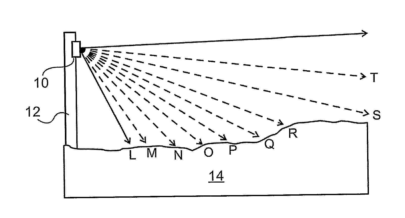
false alarm rate (FAR). The systems are based on the generation of an array of light beams projected into a two dimensional surface located generally along the line to be secured, and the detection of the distance and height of any spurious reflection from this array of light beams, by means of a detection array, detecting imaged fields of view within the surface along the line to be secured. The surface is most conveniently a plane surface, and will be so addressed henceforth, though this is not intended to limit the described systems to such planar surfaces. Such spurious reflections are assumed to arise from an intrusion object within the plane surveilled. Since the background reflection pattern without any intrusion can be acquired and stored by the system, a change in this detected background pattern can be defined as arising from a spurious reflection, and hence indicative of an intrusion. The
angular direction from which the spurious reflection originates is known from the knowledge of which particular
detector pixel has detected the spurious reflection signal, since each pixel may generally be directed to monitor a different field of view. The longitudinal position along the line of detection from which the spurious reflection is generated is known, if the particular beam which resulted in that reflection is also known. If the differently oriented beams are identifiable from each other in some way, then the illumination beam which caused the reflection detected can be determined, thus defining the position of the spurious reflection within the plane at the crossing point of the
beam direction and the direction of that field of view in which a change in the reflected illumination beam is detected. The beams can be identified by projecting them sequentially according to a predetermined timed sequence, and relating the time of detection at the pixel to that predetermined timed sequence, such that the particular transmitting beam which generated the spurious reflection is known. This is a form of
time division multiplexing whereby each
light beam illuminates the area in a separate, known time interval. Alternatively, all of the beams can be activated at the same time, each beam having an identifiable modulation applied to it. The detection circuits are adapted to identify the beam by demodulating the signal detected, and identifying the location of the beam associated with that particular modulation. Alternatively, the beams can be distinguished by providing each with a different
wavelength, or a different polarization type or orientation, and determining these characteristics to define the particular beam being detected. Any other devised form of beam identification may also be used without limiting the generality of the method.
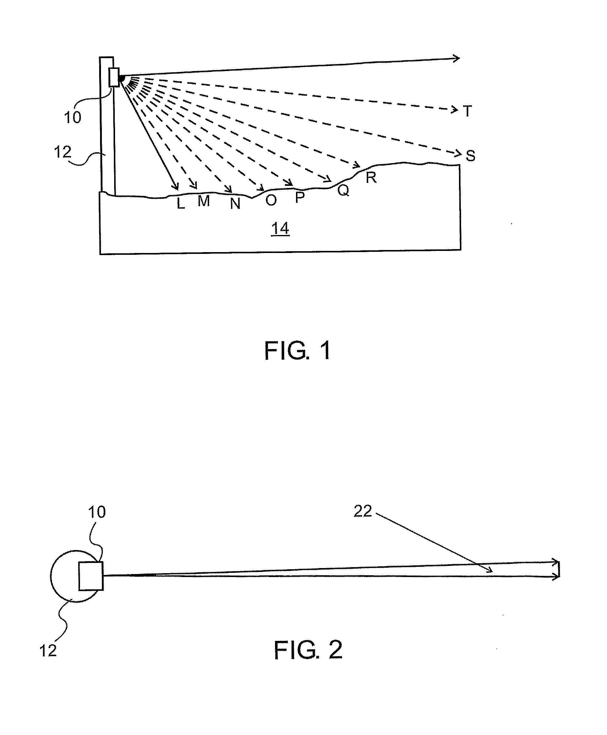
[0006]A practical method of implementing such a system is by mounting the source of illumination beams and the
detector array at spatially separated locations at the edge of the
border line plane to be surveilled, such that the
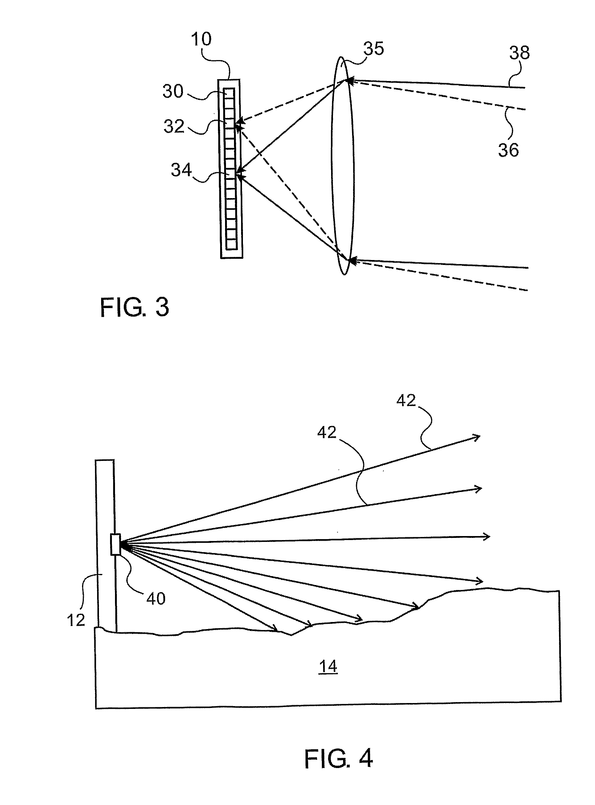
parallax between them enables the position of a reflection from within the surveilled plane to be determined. This can be easily achieved, for instance, by mounting them at different heights on the same pole or stake. A focusing objective lens may be used to direct the light from different directions onto the
linear array of pixels in the detector. The source of illuminating beams may advantageously be a
laser diode array.
