Laser gauge interferometer

a technology of interferometer and laser gauge, which is applied in the direction of instruments, measurement devices, scientific instruments, etc., can solve the problems of large measurement error, error in the measurement result of large measurement error obtained by correcting the displacement of the moving member, etc., to achieve the effect of improving measurement accuracy

Inactive Publication Date: 2011-02-24
CANON KK
View PDF4 Cites 12 Cited by
  • Summary
  • Abstract
  • Description
  • Claims
  • Application Information

AI Technical Summary

Benefits of technology

[0008]Therefore, an object of the present invention is to provide a laser gauge interferometer in which a correction e

Problems solved by technology

In the conventional structure described above, a measurement error is large.
Therefore, a result obtained by correcting the displacement of the moving member has an error because of a spatial difference of the change in refractive index of air.
Thus, when the result obtained by measurement by the measurement interferometer is corrected based on the result obtained by measurement by the correction interferometer reflecting a different ref

Method used


Image

  • Laser gauge interferometer
  • Laser gauge interferometer
  • Laser gauge interferometer

Examples


first embodiment

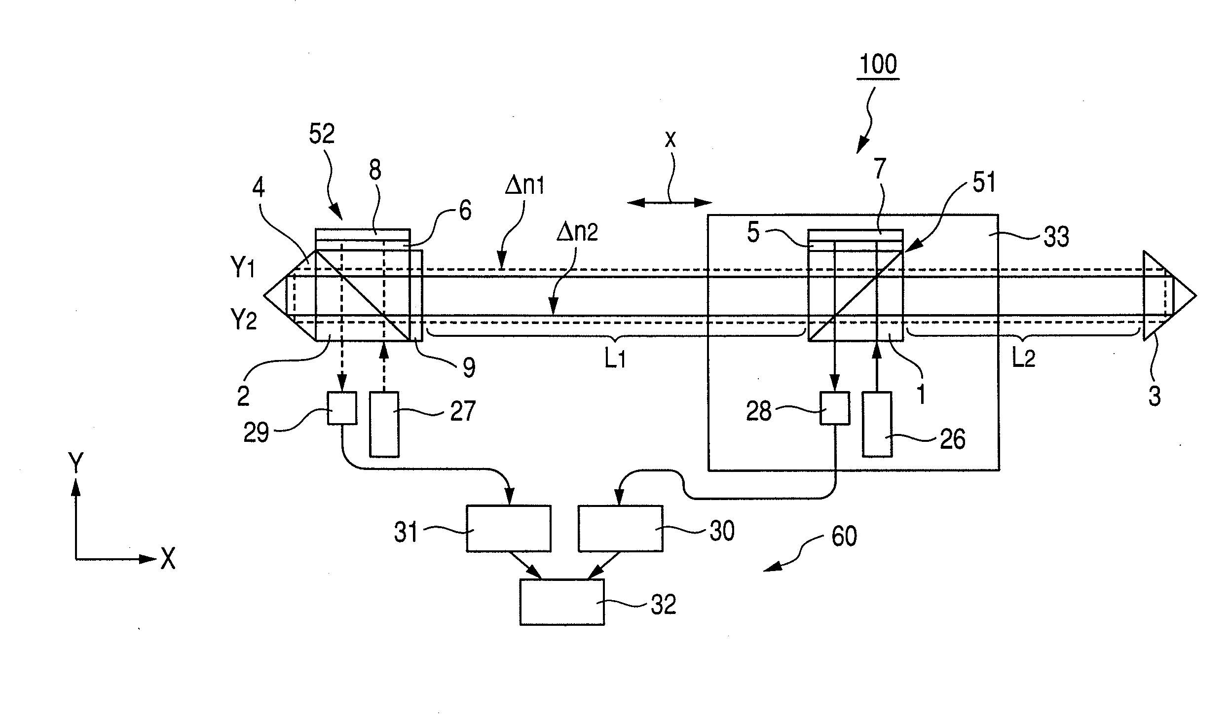
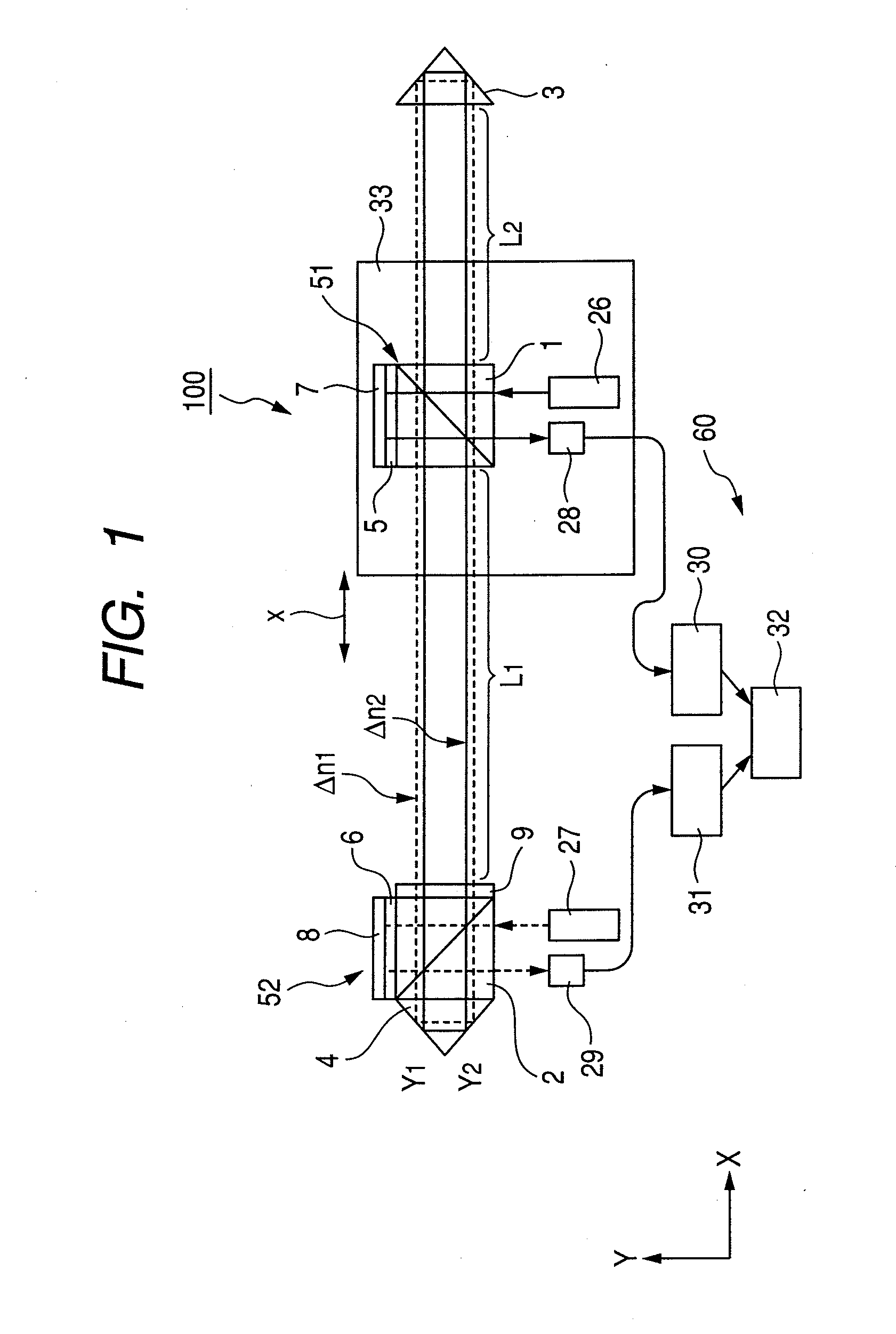
[0021]As illustrated in FIG. 1, a laser gauge interferometer 100 includes a pair of corner cubes 3 and 4 serving as a pair of reflection units for reflecting laser beams. The pair of corner cubes 3 and 4 are fixed to a base member (not shown) and maintained at a predetermined distance. In FIG. 1, a moving member 33 is, for example, a movable stage (X-stage) and linearly moved between the pair of corner cubes 3 and 4 in a direction indicated by an arrow “x”. The laser gauge interferometer 100 measures an amount of displacement of the moving member 33 which is moved, based on interference of laser beams. Note that, although a case where the reflection units are the corner cubes 3 and 4 is described, the reflection units may be rectangular mirrors.

[0022]The laser gauge interferometer 100 further includes a measurement laser oscillator (laser oscillator for measurement) 26 serving as a measurement laser light source, a correction laser oscillator (laser oscillator for correction) 27 ser...

second embodiment

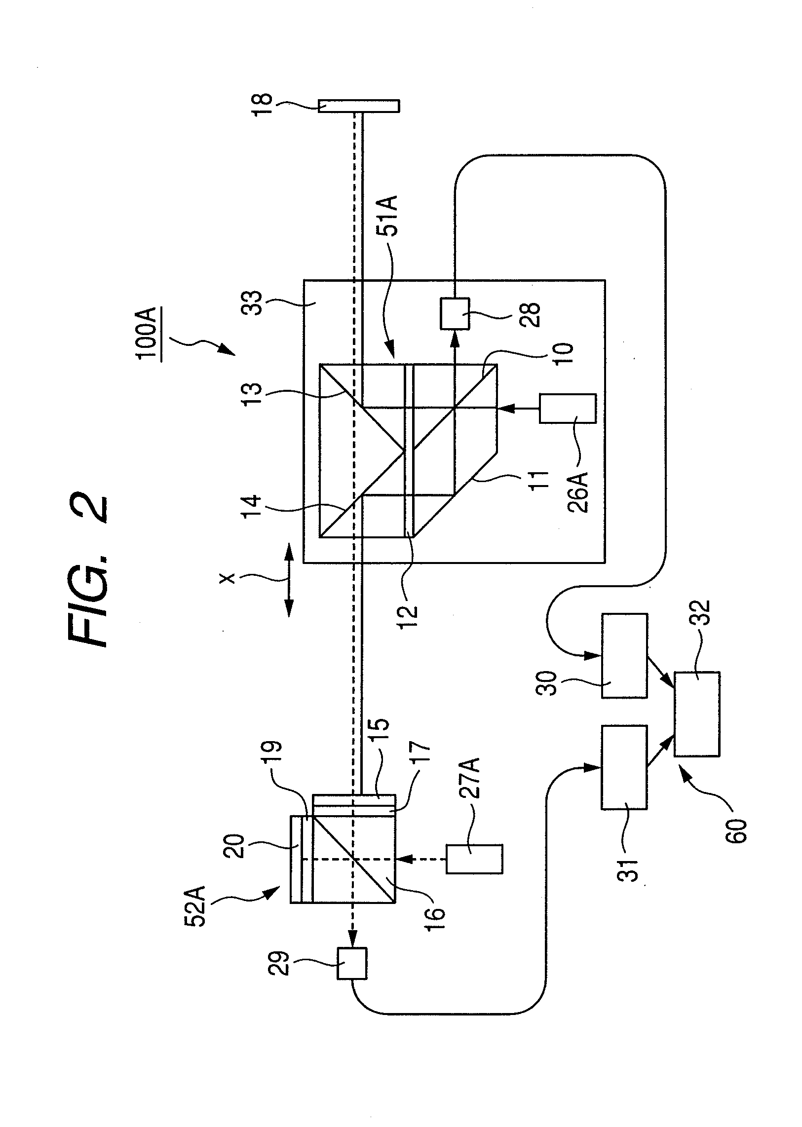
[0048]Next, referring to FIG. 2, a laser gauge interferometer 100A according to a second embodiment is described. In the second embodiment, the same structures as in the first embodiment are denoted by the same reference symbols and the description thereof is omitted. The laser gauge interferometer 100A includes a plane mirror serving as one of a pair of reflection units and a dichroic mirror 15 serving as the other of the pair of reflection units. The pair of mirrors 15 and 18 are fixed to a base member (not shown) and maintained at a predetermined distance. The moving member 33 is linearly moved between the pair of mirrors 15 and 18 in the direction indicated by the arrow “x”. The laser gauge interferometer 100A measures the amount of displacement of the moving member 33 during moving, based on the interference of laser beams. The laser gauge interferometer 100A further includes a measurement laser oscillator 26A, a measurement interferometer 51A, a correction laser oscillator 27A...

third embodiment

[0065]Next, referring to FIG. 3, a laser gauge interferometer 100B according to a third embodiment is described. In the third embodiment, the same structures as in the first and second embodiments are denoted by the same reference symbols and the description thereof is omitted. In FIG. 3, a measurement laser beam is indicated by a solid line and a correction laser beam is indicated by a broken line. In FIG. 3, the optical paths in air of the measurement laser beam and the correction laser beam are actually overlapped with each other, but slightly shifted from each other for the sake of convenience. The third embodiment is different from the second embodiment in terms of a pair of reflection units. That is, one of the reflection units is a corner cube 22 and the other of the reflection units is a pair of dichroic mirrors 23 and 24 each having an incident angle of 45°. Therefore, the correction interferometer 52B further includes a corner cube 21 provided adjacent to a surface of the ...


PUM


Abstract

There is provided a laser gauge interferometer with high measurement precision, which uses laser beam interference, includes: a measurement interferometer which generates a measurement output corresponding to a displacement of a moving member; and a correction interferometer which generates a measurement output corresponding to a change in refractive index of air at a constant reference interval. An arithmetic processing device computes a measurement target displacement amount for which the influence of the change in refractive index of air is corrected. A correction laser beam from the correction interferometer passes through the measurement interferometer and thus travels on the same optical path as an optical path of a correction laser beam from the measurement interferometer to become interference light corresponding to the change in refractive index of air through which a measurement laser beam passes, and then enters the arithmetic processing device.

Description

BACKGROUND OF THE INVENTION[0001]1. Field of the Invention[0002]The present invention relates to a laser gauge interferometer for measuring a displacement of a moving member at high precision.[0003]2. Description of the Related Art[0004]Up to now, a laser gauge interferometer has been known in which a measurement interferometer for generating a measurement output based on a displacement of a moving member which is an object to be measured and a correction interferometer for generating a measurement output based on a change in refractive index of air are combined to perform measurement while the influence of the change in refractive index of air is corrected (see Japanese Patent Application Laid-Open No. H02-001501). In the technology described in Japanese Patent Application Laid-Open No. H02-001501, a single interferometer serves as both the measurement interferometer and the correction interferometer. The interferometer is set on the moving member and moved together with the moving...

Claims


Application Information

Patent Timeline
IPC IPC(8): G01B11/02G01N21/01
CPCG01B9/0207G01B2290/60G01B2290/70G01B9/02018
Inventor SUGIURA, KEITA
Owner CANON KK
Why Eureka
Try Eureka