Lens device

a technology of a lens and a ring member, which is applied in the field of click mechanism of a ring member of a lens device, can solve the problems of increased manufacturing costs, difficult to obtain an initial click feeling, and click mechanism, and achieve the effects of accurate arrangement of each ring, reduced abrasion during a click operation, and high sliding ability

Active Publication Date: 2011-02-24
FUJIFILM CORP
View PDF2 Cites 5 Cited by
  • Summary
  • Abstract
  • Description
  • Claims
  • Application Information

AI Technical Summary

Benefits of technology

[0026]According to an eighth aspect of the invention, the lens device according to the seventh aspect, each of the first focus ring and the second focus ring may be provided on one fixed ring forming the lens barrel body. When each of the first focus ring and the second focus ring is provided on one fixed ring, it is possible to accurately arrange each of the rings.
[0027]According to the above-mentioned aspects of the invention, the click mechanism of the ring member that is rotated with respect to the lens barrel body and slides in the optical axis direction has a structure in which a plurality of elastic members for clicking is provided separately from the ring member and is arranged at the equally divided positions on the circumference of the lens barrel body and the contact portion which comes into contact with the convex portion of the elastic member for clicking is formed in the central portion of the inner circumferential surface of the ring member. According to this structure, it is possible to select a material with high slidability for the elastic member for clicking and reduce abrasion during a click operation. In addition, it is possible to prevent one-sided abrasion due to the inclination of the ring member during a sliding operation and maintain a desired click force.

Problems solved by technology

However, the click mechanism has the following problems.
The click mechanism has a problem in that it is difficult to obtain an initial click feeling with the use of the first focus ring 4.
Therefore, in order to determine an optimal click force, it is necessary to manufacture first focus ring samples including the cutouts 4B with different thicknesses, which results in an increase in manufacturing costs.

Method used


Image

  • Lens device
  • Lens device
  • Lens device

Examples


embodiments

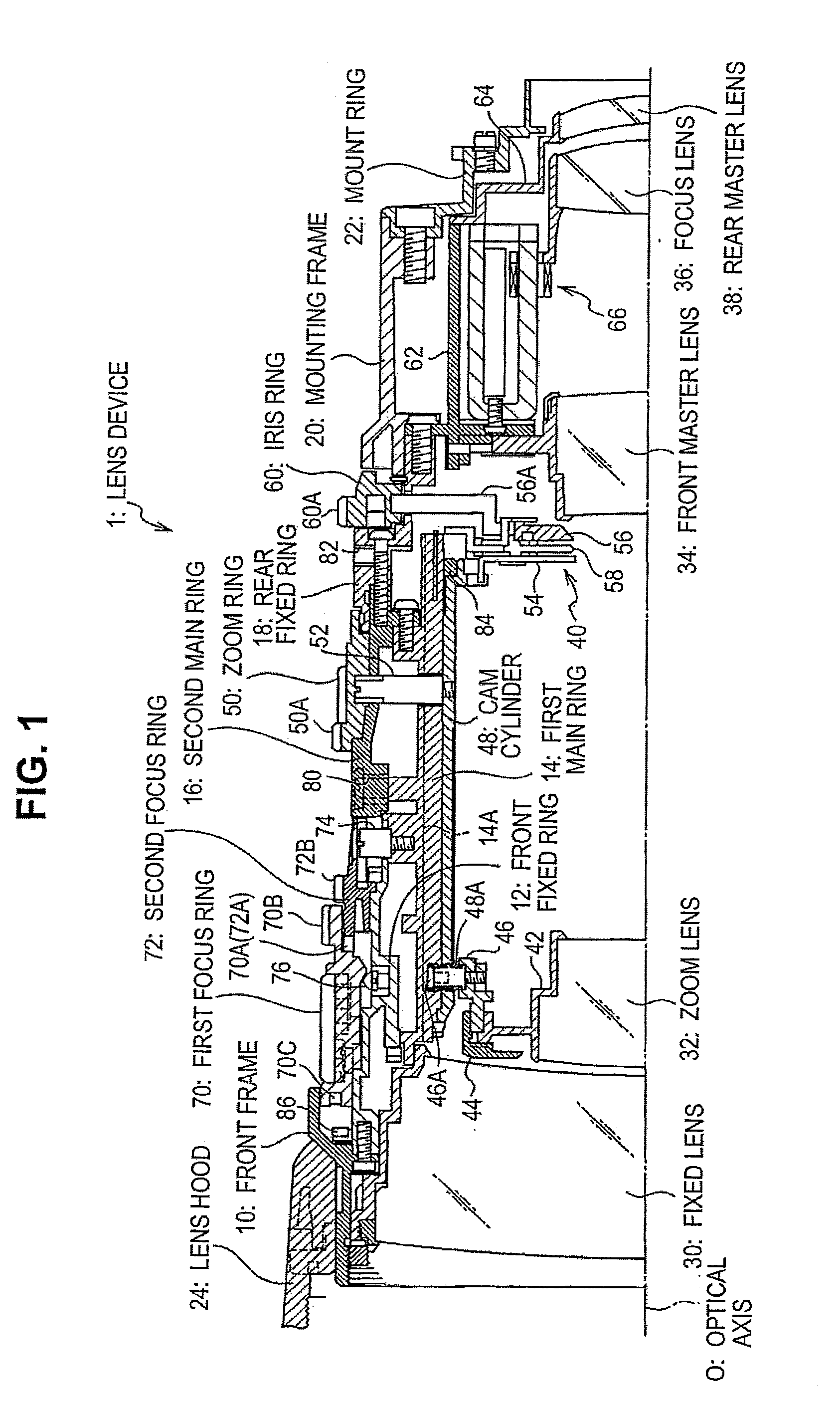
[0082]Next, the click mechanism of the first focus ring 70 applied to the lens device 1 having the above-mentioned structure will be described in detail.

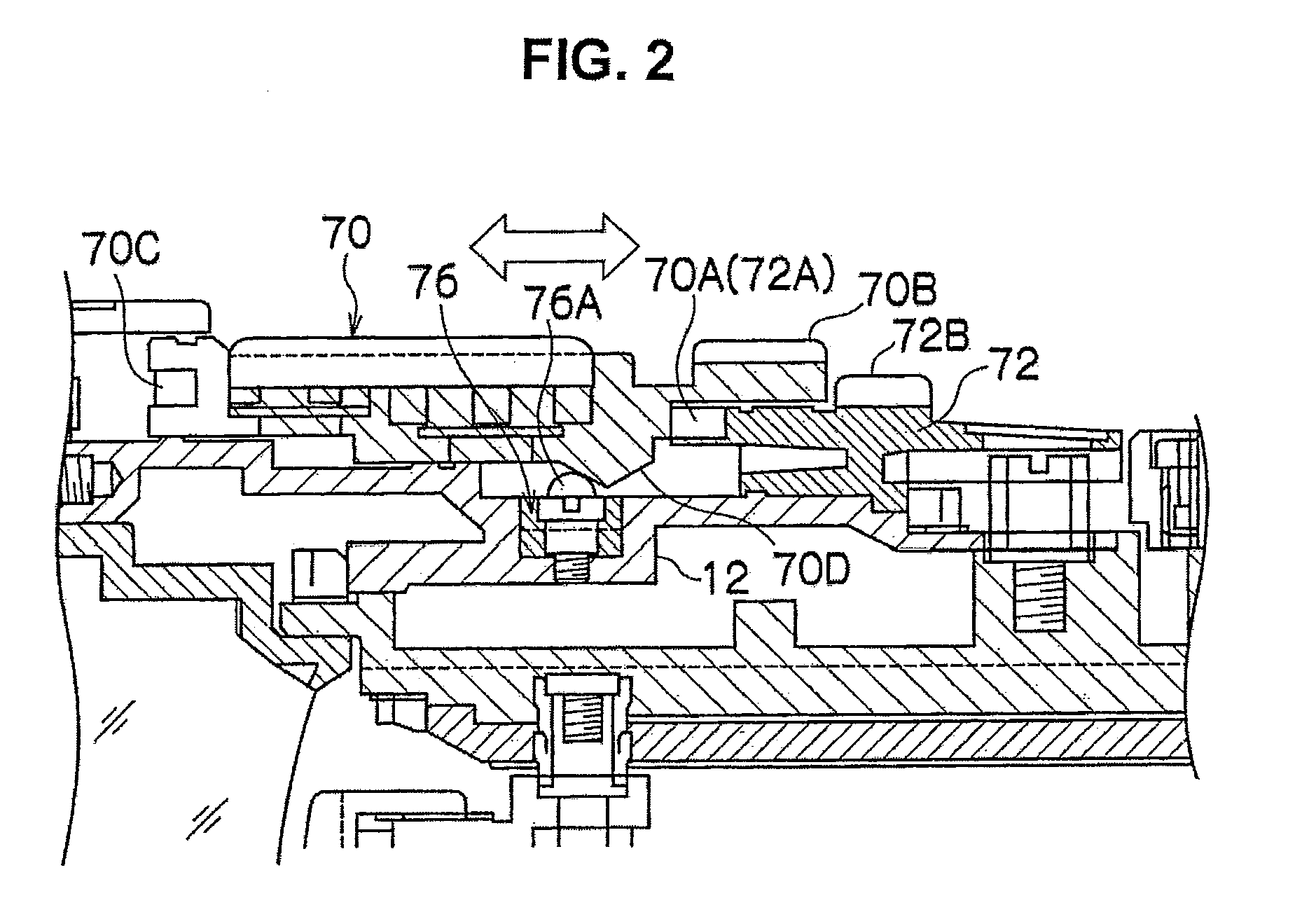
[0083]FIG. 2 is an enlarged side cross-sectional view illustrating a main part of the lens device shown in FIG. 1.

[0084]The front fixed ring 12 forming a portion of the lens barrel body is made of an aluminum alloy. The elastic members 76 for clicking are provided at three equally divided portions on the circumference of the front fixed ring 12.

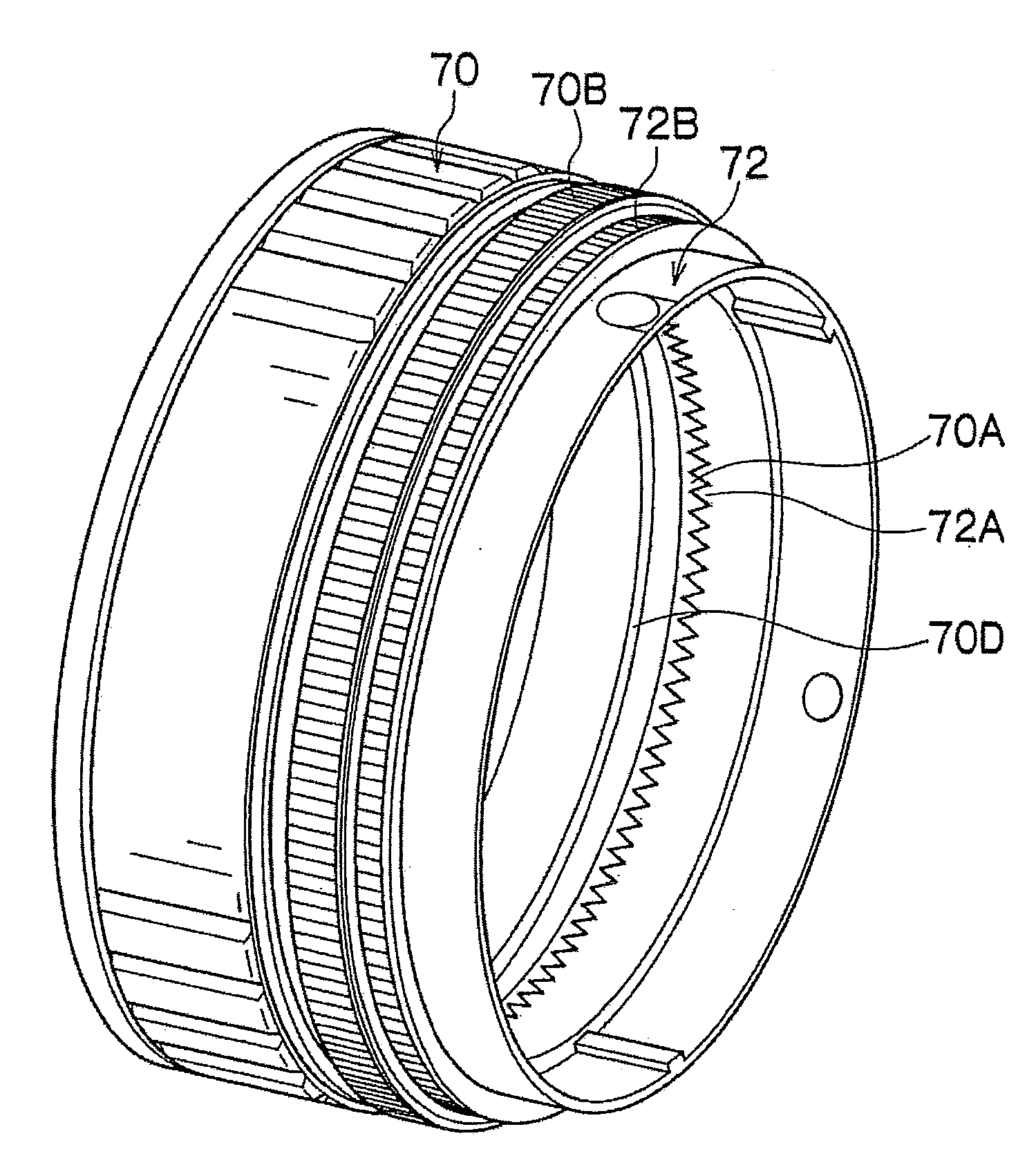
[0085]A contact portion 70D with a triangular shape in a cross-sectional view having two inclined planes is formed substantially at the center of the inner circumferential surface of the first focus ring 70.

[0086]The first focus ring 70 is provided such that it can slide in the direction of an arrow shown in FIG. 2 (optical axis direction). When the first focus ring 70 slides and the contact portion 70D of the first focus ring 70 is moved to the position (hereinafter, referred to as a “first ...


PUM


Abstract

Disclosed is a lens device including a click mechanism of a ring member that is rotated with respect to a lens barrel body, slides in the optical axis direction, has high slidability during a click operation and high durability, and can prevent one-sided abrasion due to the inclination of the ring member. A click mechanism of a first focus ring includes: elastic members for clicking provided at three equally divided positions on the circumference of a front fixed ring of a lens barrel body; and a contact portion that is formed in a central portion of the inner circumferential surface of the first focus ring and comes into contact with a convex portion of the elastic member for clicking. The elastic member for clicking is made of polyacetal with high slidability. Therefore, it is possible to reduce the abrasion of the elastic member for clicking during a click operation.

Description

CROSS-REFERENCE TO RELATED APPLICATIONS[0001]This application is based upon and claims the benefit of priority from the Japanese Patent Application No. 2009-192302 filed on Aug. 21, 2009; the entire contents of which are incorporated herein by reference.BACKGROUND OF THE INVENTION[0002]1. Field of the Invention[0003]The present invention relates to a lens device, and more particularly, to a click mechanism of a ring member of a lens device.[0004]2. Description of the Related Art[0005]JP-A-2007-219023 discloses a lens device used in a portable ENG (Electronic News Gathering) camera for television news. The lens device has a first MF mode that outputs an absolute position signal corresponding to the rotational position of a focus ring as an instruction to move the focus lens and a second MF mode that outputs a relative position signal corresponding to the amount of rotation of the focus ring as an instruction to move the focus lens, during a manual focus (MF) operation that manually o...

Claims


Application Information

Patent Timeline
Patent Type & Authority Applications(United States)
IPC IPC(8): G02B7/02
CPCG02B7/282G02B7/102
Inventor MORI, YOSHITAKA
Owner FUJIFILM CORP
Why Eureka
Try Eureka