System and method for transferring data over full-duplex differential serial link

a serial link and data transfer technology, applied in the field of data transfer systems, can solve the problems of stringent electromagnetic interference (emi) requirements applied to such video systems, and achieve the effect of low electromagnetic interference (emi) and high speed

Active Publication Date: 2011-02-24
MAXIM INTEGRATED PROD INC
View PDF2 Cites 16 Cited by
  • Summary
  • Abstract
  • Description
  • Claims
  • Application Information

AI Technical Summary

Benefits of technology

An aspect of the invention relates to a data transmission technique. According to the technique, relatively high speed serial data is transmitted using differential signaling in a forward channel by way of a communications link. Additionally, relatively low speed serial data is differentially modulated onto the forward channel signal for transmission in a reverse channel by way of the communications link. By utilizing full differential modulation in both the forward and reverse channels, the resulting signal has a common mode voltage that is substantially constant. This results in relatively low electromagnetic interference (EMI).
Furthermore, the spectral content of the resulting signal associated with the high speed serial data may be substantially non-overlapping with the spectral content of the resulting signal associated with the low speed serial data. This allows for the recovery of the high speed data and low speed data with minimal interference. Moreover, the differential signaling lends itself for the transfer of data via a relatively inexpensive communications link, such as a twisted wire pair or parallel printed circuit board (PCB) traces. Embodiments are described herein that implement this data transmission technique.

Problems solved by technology

In addition, due to the fact that automobile and aircraft video systems coexist with other sensitive systems (e.g., aircraft flight control and navigation systems), generally stringent electromagnetic interference (EMI) requirements are applied to such video systems.

Method used


Image

  • System and method for transferring data over full-duplex differential serial link
  • System and method for transferring data over full-duplex differential serial link
  • System and method for transferring data over full-duplex differential serial link

Examples


Embodiment Construction

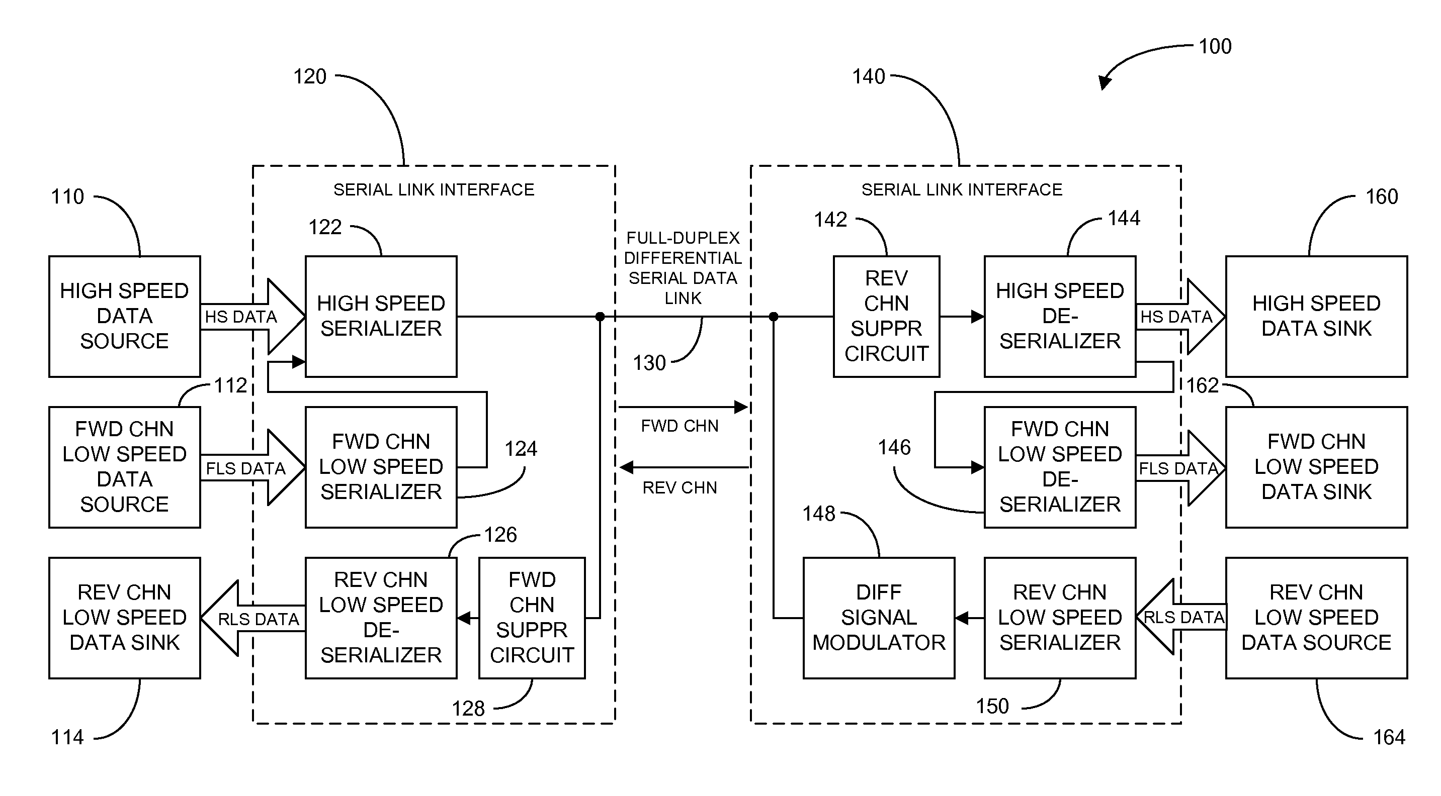
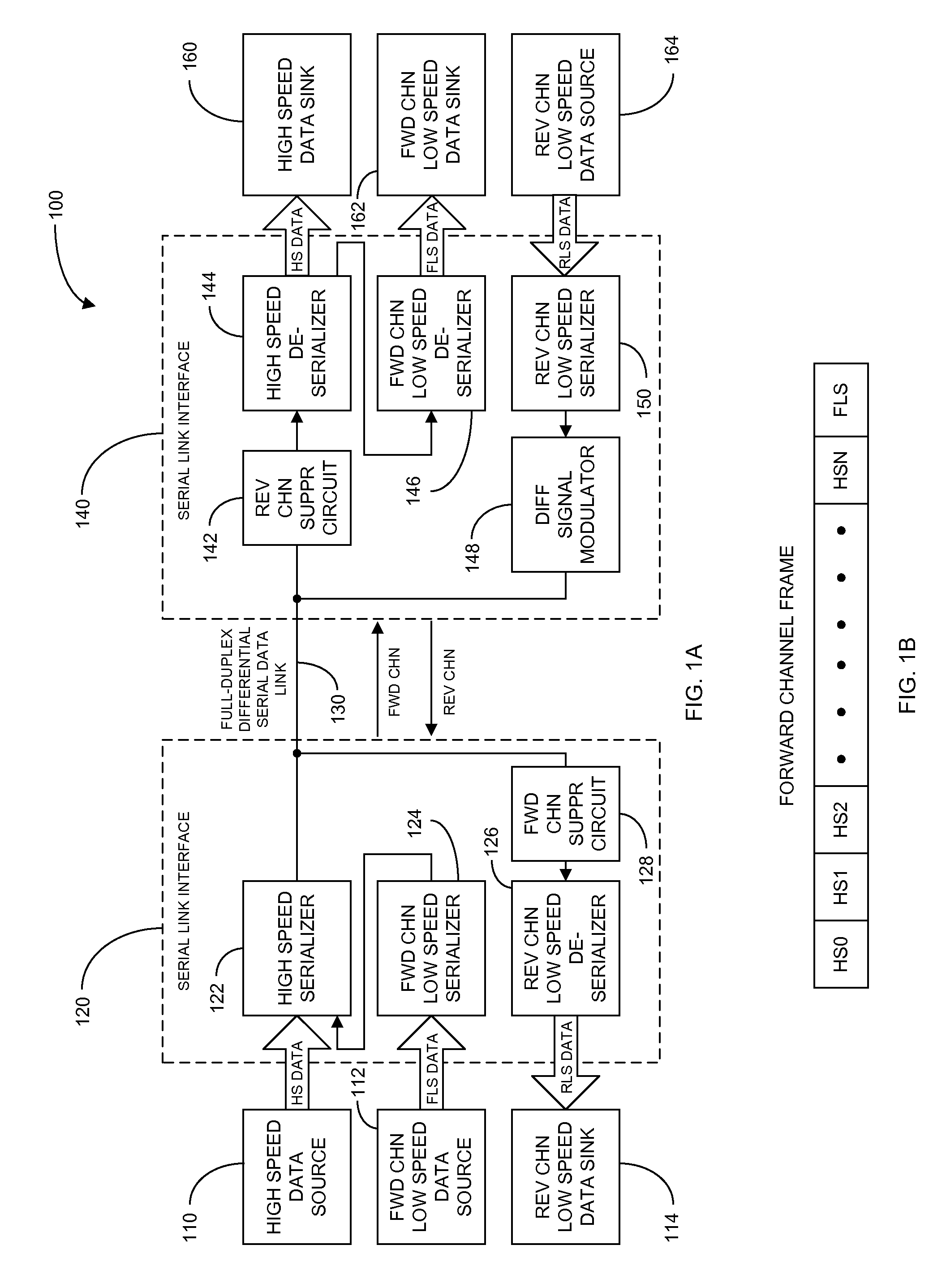
FIG. 1A illustrates a block diagram of an exemplary system 100 for transferring data in accordance with an embodiment of the invention. In summary, the system 100 employs a data transmission technique for providing a full-duplex differential serial data link. In particular, the data transmission technique entails transmitting high speed data (e.g., video data) and low speed data (e.g., audio and / or control data) in a forward channel simultaneously with the transmission of low speed data (e.g., control data) in a reverse channel. Additionally, the full-duplex transmission of the data may occur over a relatively inexpensive physical medium, such as a twisted conductor pair or parallel printed circuit board (PCB) traces. Furthermore, the data transmission may be in full differential signaling for improved EMI protection.

More specifically, the system 100 comprises a high speed data source 110, a forward channel (FWD CHN) low speed data source 112, and a reverse channel (REV CHN) low spe...


PUM


Abstract

A data transmission technique where high speed data is transmitted differentially in a forward channel by way of a serial link, and relatively low speed data is differentially modulated onto the forward channel signal for transmission in a reverse channel via the link. By utilizing differential modulation in both forward and reverse channels, the resulting signal has a common mode voltage that is substantially constant, resulting in low EMI. The spectral content of the signal associated with the high speed data may be substantially non-overlapping with the spectral content of the signal associated with the low speed data. This facilitates the recovery of the high speed data and low speed data with minimal interference. The differential signaling lends itself for communicating data via an inexpensive medium, such as twisted wire pair or parallel PCB traces. The data transmission technique applies to various communication network topologies: point-to-point, daisy-chain, and point-to-multiple points.

Description

FIELD OF THE INVENTIONThis invention relates generally to data transfer systems, and in particular, to a system and method for transferring data over a full-duplex differential serial link.BACKGROUND OF THE INVENTIONIn many applications, high speed data needs to be transferred from a source to a sink substantially simultaneously with the transfer of low speed data. For example, in video applications, video data (e.g., relatively high speed data) needs to be transferred from a video source (e.g., a camera) to a video sink (e.g., a display). Simultaneously with the transfer of the video data, control data (e.g., relatively low speed data) needs to be transferred, in both directions, between the video source and the video sink. For example, control data from the video source to the video sink may dictate how the video data is to be displayed. While, for example, control data from the video sink to the video source may dictate the view angle, exposure, focus of the camera, or status of ...

Claims


Application Information

Patent Timeline
Patent Type & Authority Applications(United States)
IPC IPC(8): H04L5/14
CPCH04L25/0272H04L5/14
Inventor WU, QIANGYILMAZER, CAGLARONER, MUSTAFA ERTUGRUL
Owner MAXIM INTEGRATED PROD INC
Why Eureka
Try Eureka