Blade pitch lock device

a turbine blade and locking device technology, applied in the direction of propellers, propulsive elements, water-acting propulsive elements, etc., can solve the problems of complex and expensive both to set up and maintain, and the design of a wind power plant is not able to cop

Inactive Publication Date: 2011-02-24
GE WIND ENERGY NORWAY
View PDF5 Cites 22 Cited by
  • Summary
  • Abstract
  • Description
  • Claims
  • Application Information

AI Technical Summary

Benefits of technology

[0010]c. a locking device having a mechanical locking which is independent of any additional power supply in order to lock the ...

Problems solved by technology

For this reason, some sort of locking mechanism for the blades is needed, and is especially important during maintenance work where events of accidental rotation may cause substantial damages to components and indeed to personnel performing such maintenance on the wind turbine.
Another reason to shut down the turbine is extreme wind conditions where the design of a wind ...

Method used


Image

  • Blade pitch lock device
  • Blade pitch lock device
  • Blade pitch lock device

Examples


Embodiment Construction

[0023]The following detailed description, and the examples contained therein, are provided for the purpose of describing and illustrating certain embodiments of the invention only and are not intended to limit the scope of the invention in any way.

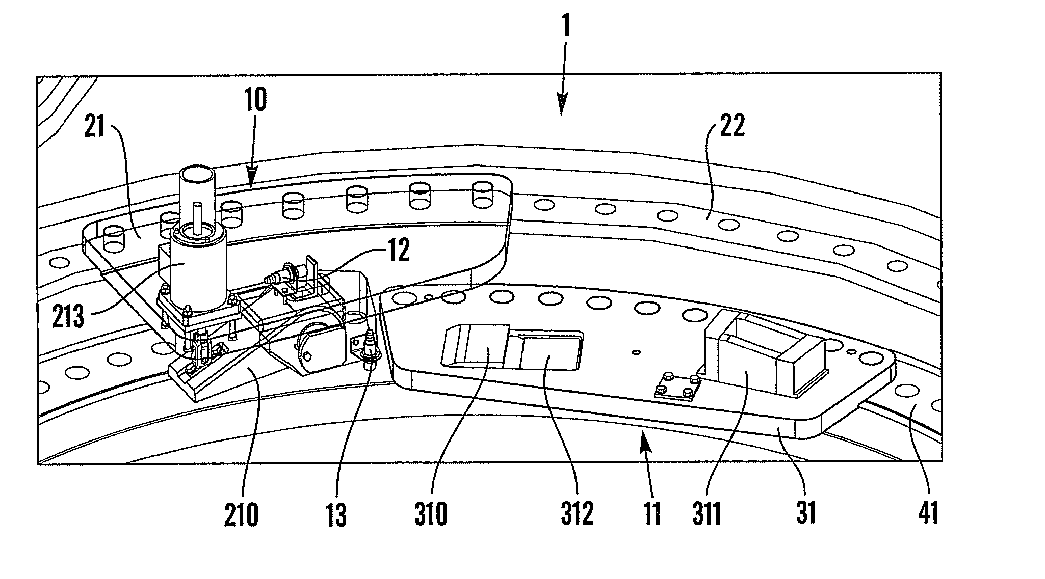
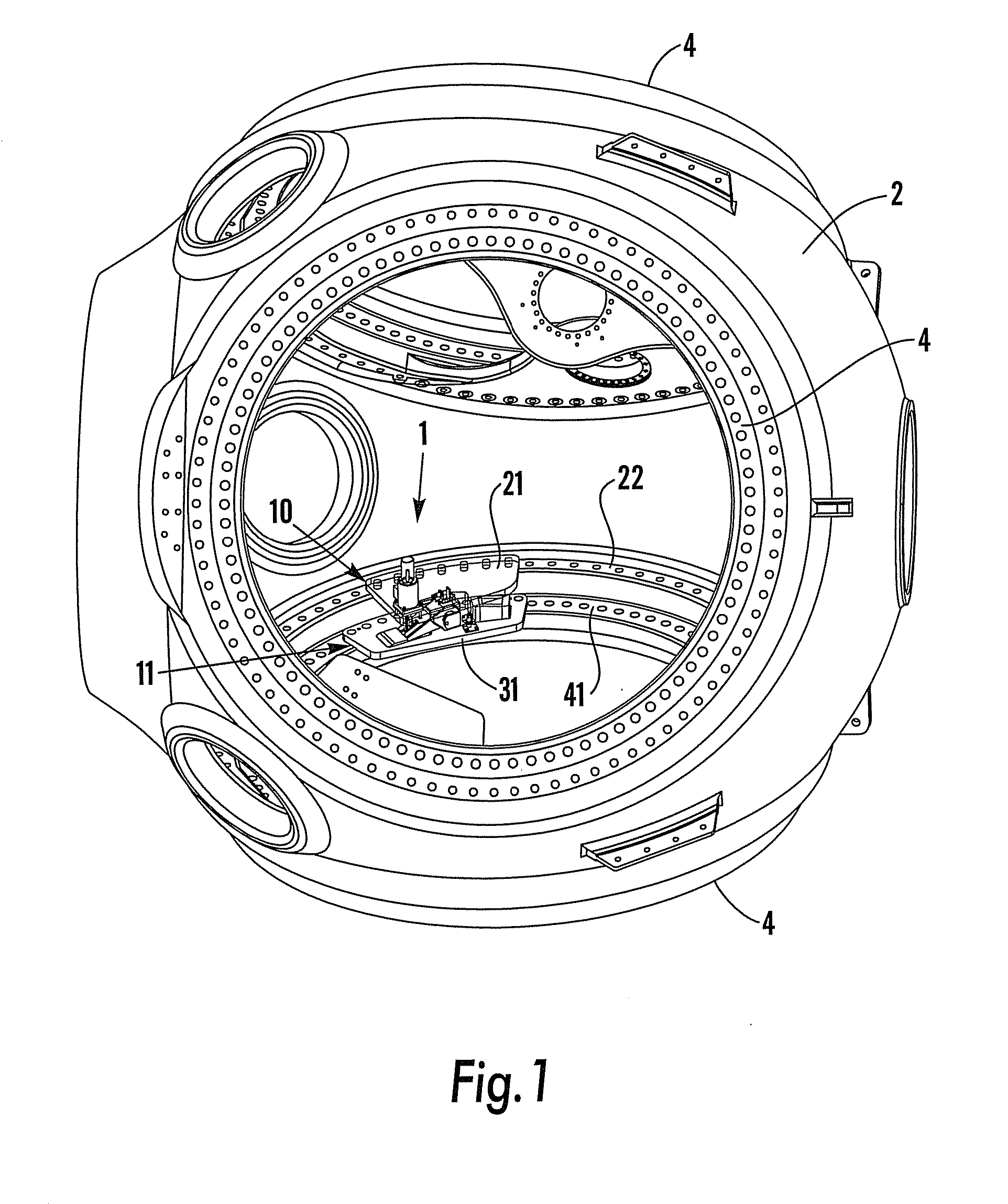
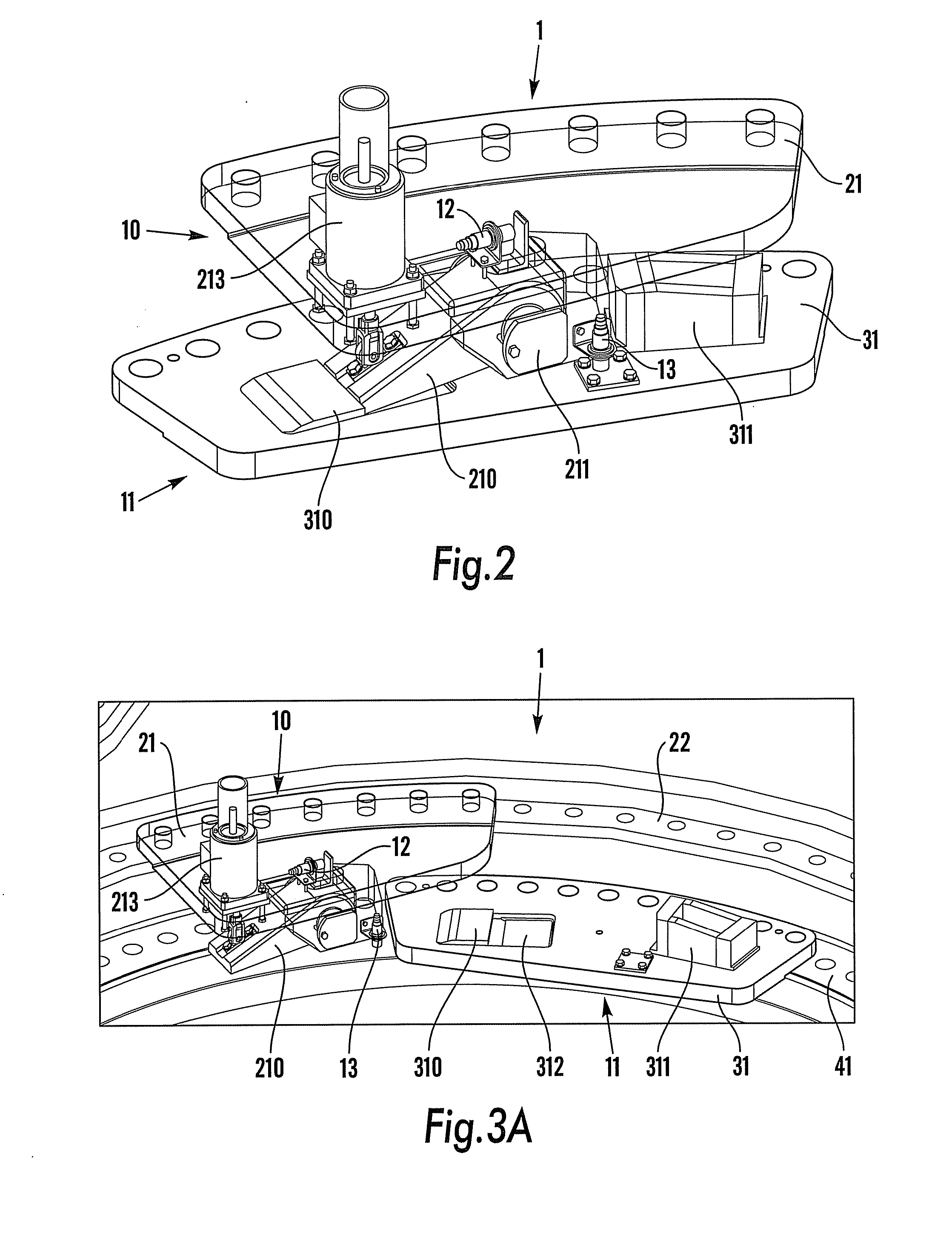
[0024]FIG. 1 illustrates a rotor hub 2 of a wind power plant with three pitch bearings 4, each for receiving a turbine blade (not shown). Each pitch bearing 4 includes an annular flange 22 which is connected to the hub 2, and an annular bearing ring 41 configured for operable connection with the rotor blade. One pitch bearing 4 is seen to comprise a locking device 1 according to the present invention. The locking device 1 in FIG. 1 is shown in a locked mode, preventing the blade (not shown) from rotating around its longitudinal axis relative to the rotor hub 2. As is illustrated by FIG. 1, the locking device 1 comprises one hub part 10 which is connected to the flange 22 and one blade part 11 which is connected to the bearing ring 41 of th...


PUM


Abstract

A locking device for locking a turbine blade of a wind power plant at a predetermined pitch angle, which wind power plant includes a rotor hub and at least one turbine blade where the blade root of the at least one turbine blade is connected to the rotor hub through a pitch bearing so that the pitch angle of the at least one turbine blade is adjustable by turning of the at least one turbine blade about its longitudinal axis relative to the rotor hub and wherein the device for locking the turbine blade includes a mechanical snap-in mechanism which in a locked position prevents the at least one turbine blade from turning about its longitudinal axis thus fixating the at least one turbine blade in the predetermined pitch angle.

Description

BACKGROUND OF THE INVENTION[0001]The present invention relates to a device for locking a turbine blade of a wind power plant at a predetermined pitch angle which wind power plant comprises a rotor hub and at least one turbine blade where the blade root of the at least one blade is connected to the rotor hub through a pitch bearing so that the pitch angle of the at least one blade is adjustable by turning of the at least one blade about its longitudinal axis relative to the rotor hub.[0002]Adjusting the pitch angle of turbine blades is a way of controlling the rotational speed (rpm) of a wind turbine. In order to reduce the load or completely stop rotation the blades are directed to a feathered position where the wind will not engage with the blade and the blades are urged to stall and rotation of the turbine will decrease and / or stop. Once turbine is stopped and the blades have been put into a parked position it is important that the pitch angle of the blades does not accidentally c...

Claims


Application Information

Patent Timeline
IPC IPC(8): F03D7/00F03D11/00
CPCF05B2260/79F03D7/0224Y02E10/723Y02E10/72F03D7/022F03D1/0664
Inventor LINDBERG, MIKAELHEDBERG, JOHAN
Owner GE WIND ENERGY NORWAY
Why Eureka
Try Eureka