Laminoplasty System

a laminoplasty and system technology, applied in the field of laminoplasty system, can solve the problems of increasing time and complexity of the procedure, increasing the risk of pseudoarthrosis and accelerating degeneration at the levels, and reducing the surgical time. , the effect of simplifying laminar fixation and fusion

Active Publication Date: 2011-02-24
KHANNA ROHIT
View PDF1 Cites 15 Cited by
  • Summary
  • Abstract
  • Description
  • Claims
  • Application Information

AI Technical Summary

Benefits of technology

[0008]The present invention relates a laminar fusion and fixation system following either open door or double door laminoplasty technique. This system with the spacer and plate reduces surgical time and simplifies laminar fixation and fusion if needed after laminoplasty.

Problems solved by technology

Cervical stenosis with spinal cord compression and consequent myelopathy is a very common problem encountered by the spine surgeon.
The main drawback of this technique is the increased time and complexity of the procedure as well as the risk of pseudoarthrosis and accelerated degeneration at the levels above and below the fusion.
The drawback of a simple laminectomy is the risk of late clinical deterioration form either kyphosis or postlaminectomy scar formation.
Laminectomy with facet fusion decreases the risk of kyphosis but it also decreases the range of motion in the spine and increases the risk of accelerated degeneration at the levels above and below the fusion.

Method used


Image

  • Laminoplasty System
  • Laminoplasty System
  • Laminoplasty System

Examples


Embodiment Construction

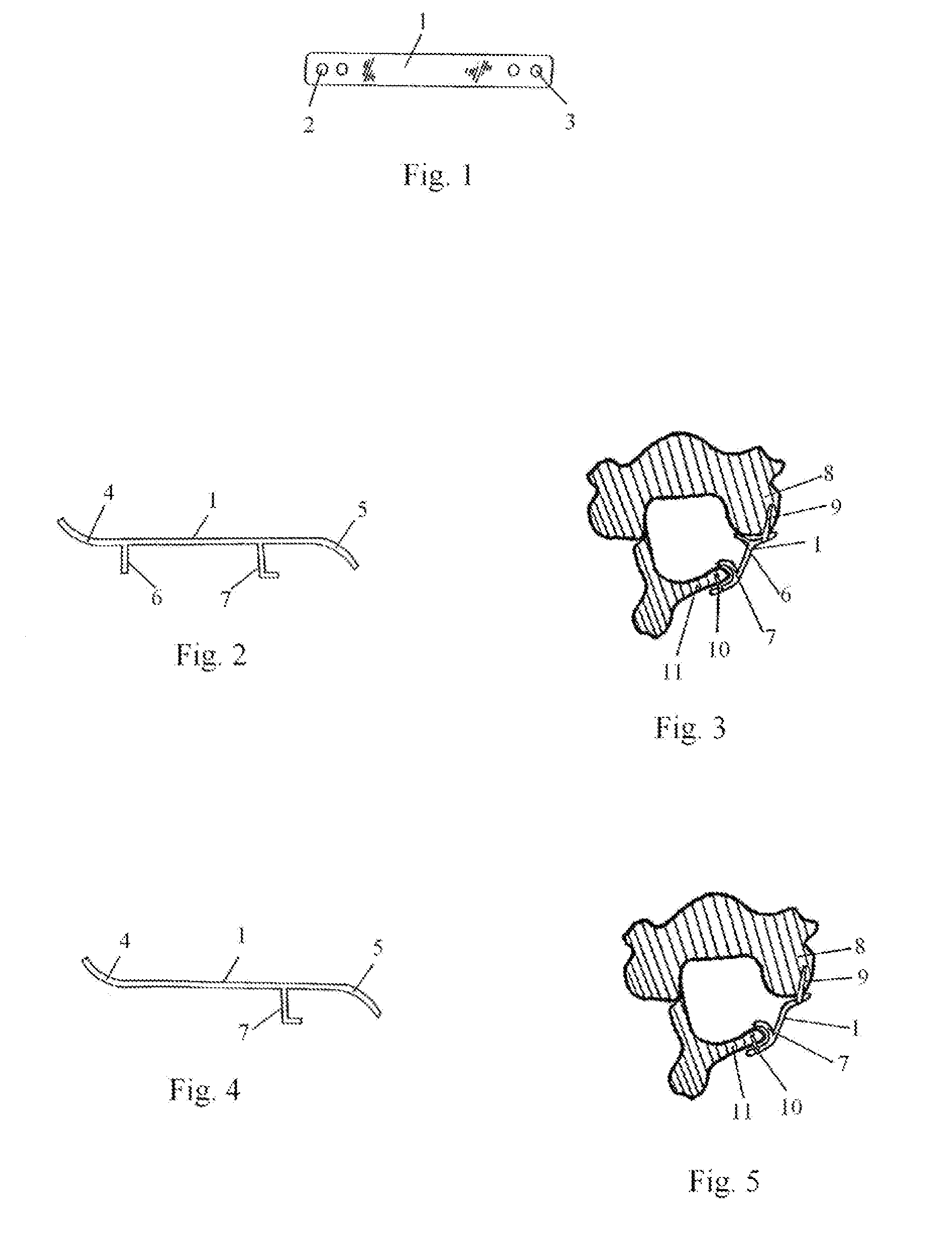
[0064]The technique of open-door laminoplasty stabilization without laminar fusion undertaken with the use of the plates is illustrated in FIGS. 1-5. The plate has a top surface 1 with bone screw holes at the ends 2 and 3. The ends have an upward angle at one end 4 and downward angle at the other 5. In one embodiment as seen on the side view in FIG. 2, there is a hook appendage 7 perpendicular to the plate to engage the lamina at one end and a straight appendage 6 at the other end to secure to the facet. In another embodiment of the plate as seen in FIG. 4, there is only one appendage 7 at the end prior to the downward angle of the plate. The implanted construct is seen in FIGS. 3 and 5. The plate is secured to the lamina 11 via bone screw 10 and facet 8 via bone screw 9. The hook 7 secures the lamina in the displaced laminoplasty position. As seen in FIG. 3, the additional straight appendage 6 at the facet end allows the plate to rest on the facet 8.

[0065]In another embodiment, the...


PUM


Abstract

Fixation devices and methods for stabilization of the lamina after laminoplasty are described. The device comprises of a plate with several holes that receive bone fasteners. The plate is curved at the ends to contour to the vertebral structure and has appendages to engage the displaced lamina in a fixed position. Alternatively, the plate has a bone fusion spacer in the middle to engage and fuse the lamina in the displaced position. Several methods of dynamically stabilizing the lamina after either the open door, double door or expansive laminoplasty technique are provided.

Description

RELATED U.S. APPLICATION DATA[0001]Division of application Ser. No. 10 / 035,281, filed on Jan. 3, 2002, now abandoned, and continuation of application Ser. No. 10 / 299,624, filed on Nov. 19, 2002, now U.S. Pat. No. 6,600,007.BACKGROUND OF THE INVENTION[0002]Cervical stenosis with spinal cord compression and consequent myelopathy is a very common problem encountered by the spine surgeon. The usual cause of multilevel cervical stenosis is spondylosis and / or ossification of the posterior longitudinal ligament. Surgical decompression either through an anterior or posterior approach can be undertaken.[0003]An anterior approach usually involves multilevel corpectomy with fusion and stabilization. The main drawback of this technique is the increased time and complexity of the procedure as well as the risk of pseudoarthrosis and accelerated degeneration at the levels above and below the fusion.[0004]A posterior approach has traditionally involved a simple laminectomy, laminectomy with facet f...

Claims


Application Information

Patent Timeline
Patent Type & Authority Applications(United States)
IPC IPC(8): A61B17/88A61B17/70
CPCA61B17/7071
Inventor KHANNA, ROHIT
Owner KHANNA ROHIT
Why Eureka
Try Eureka