Expansion tank for vehicle cooling system

a technology for expansion tanks and cooling systems, which is applied in the direction of mechanical equipment, machines/engines, light and heating equipment, etc., can solve the problem of not being able to locate the fluid level line of the expansion tank

Active Publication Date: 2011-03-03
INT ENGINE INTPROP CO LLC
View PDF14 Cites 6 Cited by
  • Summary
  • Abstract
  • Description
  • Claims
  • Application Information

AI Technical Summary

Problems solved by technology

Due to engine packaging constraints, the low fluid level line of the expansio...

Method used


Image

  • Expansion tank for vehicle cooling system
  • Expansion tank for vehicle cooling system
  • Expansion tank for vehicle cooling system

Examples


first embodiment

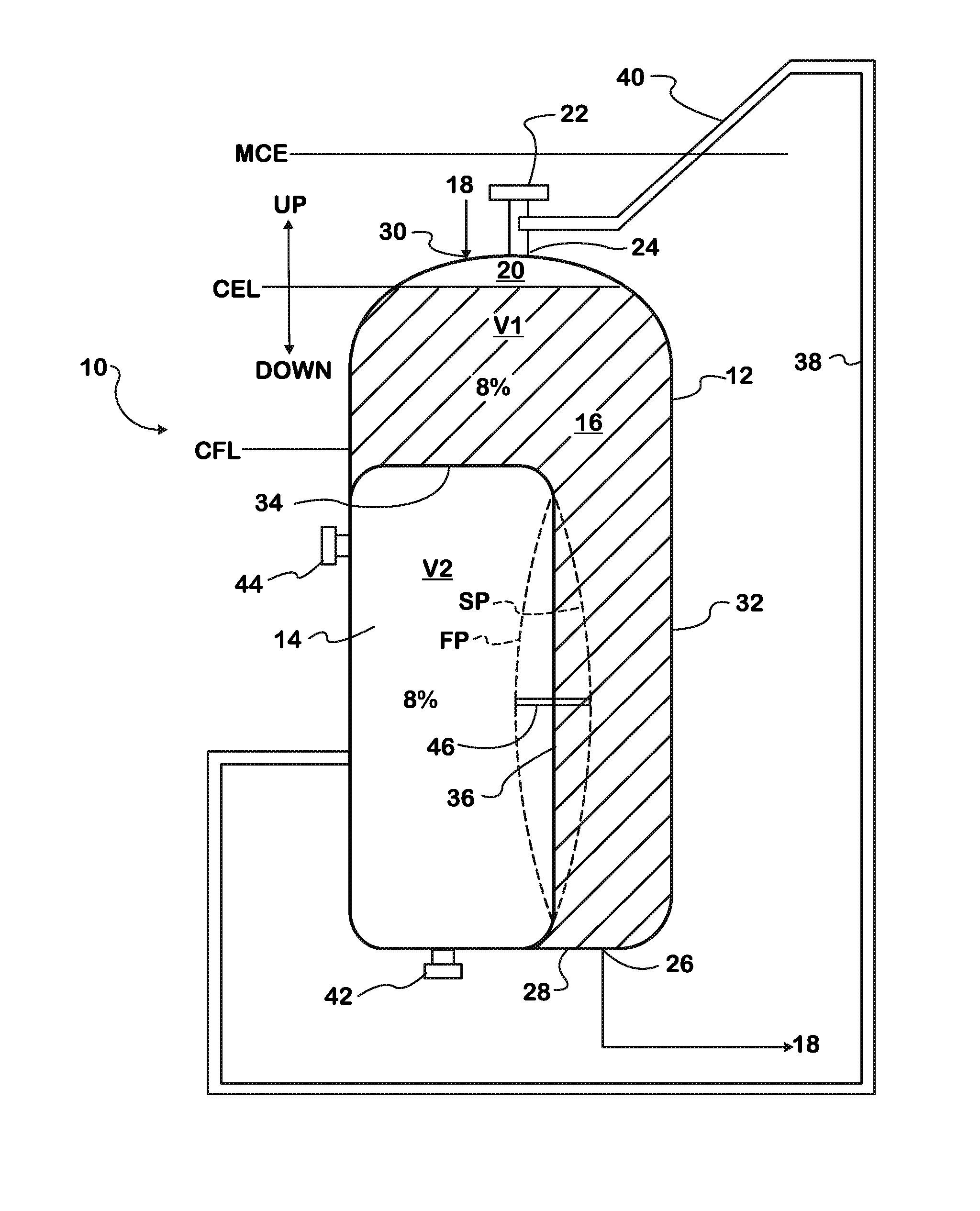
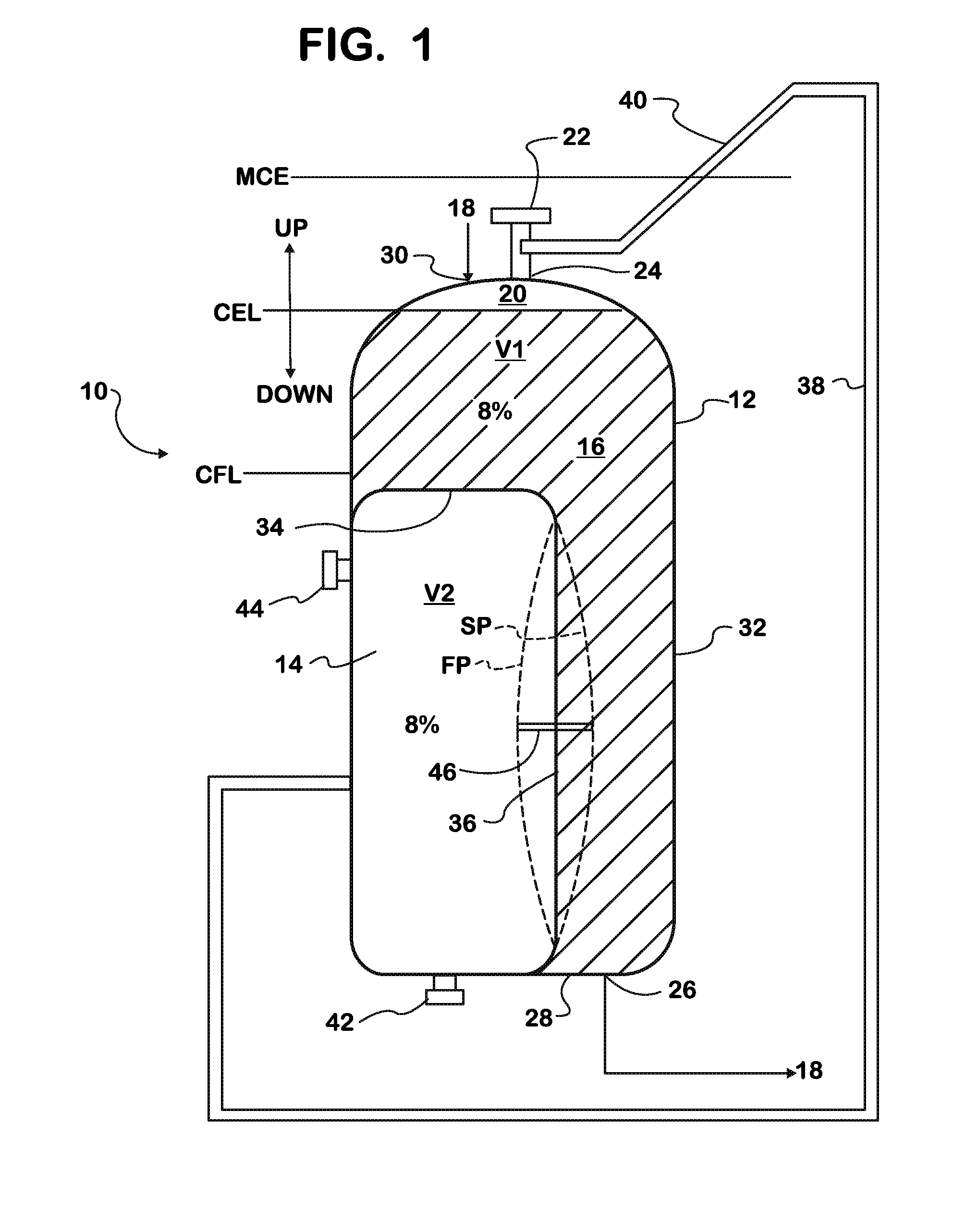
[0010]Referring now to FIG. 1, an expansion tank is indicated generally at 10 and has a tank body 12 with a first volume V1, and a bladder 14 disposed in the tank body 12 and having a second volume V2. The tank body 12 is generally cylindrical, however other shapes and configurations are possible. The first volume V1 is configured to receive liquid coolant 16 of a cooling system 18. The cooling system 18 is associated with an engine (not shown) that has a coolant fill level (CFL) and a maximum coolant elevation (MCE).

[0011]The coolant 16 inside the expansion tank 10 forms a coolant elevation level (CEL) within the tank body 12, and is dependent upon the amount of coolant and the thermal expansion of the coolant. As will be discussed below, the CEL is also dependent on the bladder 14. During operation of the cooling system 18, the CEL needs to be at least as high in elevation as the CFL of the vehicle.

[0012]The second volume V2 in the bladder 14 is configured to be filled with air an...

second embodiment

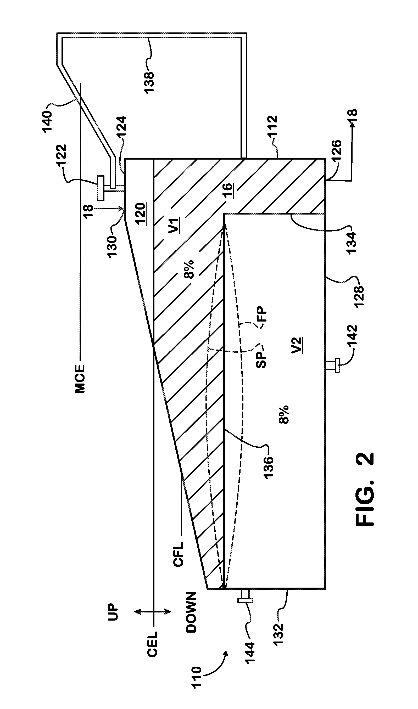
[0023]Turning now to FIG. 2, expansion tank is indicated generally at 110 and is generally similar in operation to the expansion tank 10. The expansion tank 110 has a tank body 112 with a first volume V1 of coolant 16, and a bladder 114 disposed in the tank body 112 having a second volume V2. The tank body 112 is generally truncated prism-shaped, however other shapes are possible. The first volume V1 is configured to receive the liquid coolant 16 of the cooling system 18. The cooling system 18 is associated with the engine (not shown) having a coolant fill level (CFL) and maximum coolant elevation (MCE). During operation of the cooling system 18, the CEL needs to be at least as high in elevation as the CFL of the engine.

[0024]The second volume V2 in the bladder 114 is configured to be filled with air. An upper volume 120 of the tank body 12 located above the CEL is also filled with air. It is possible that the second volume V2 and the upper volume 120 can be filled with a fluid othe...


PUM


Abstract

An expansion tank (10) for a vehicle cooling system (18) of an engine using a liquid coolant (16) includes a tank body (12) defining a first volume (V1) containing coolant (16), wherein the coolant defines a variable coolant elevation level (CEL) within the tank body. The tank body (12) also defines an upper volume (20) containing air. A bladder (14) is disposed in the tank body (12) and defines a second volume (V2) containing air. The bladder (14) includes a flexible membrane (36) actuated by an actuator (46). When the engine is stopped or is below a predetermined temperature, the flexible membrane (36) is moveable to a first position (FP) which lowers the coolant elevation level (CEL), and when the engine is started or reaches a predetermined temperature, the flexible membrane (36) is moveable to a second position (SP) which raises the coolant elevation level. A communicating line (38) is in fluid communication between the upper volume (20) and the second volume (V2) to fluidly communicate air therebetween.

Description

BACKGROUND[0001]Embodiments described herein generally relate to vehicle cooling systems. More specifically, embodiments described herein relate to an expansion tank of a vehicle cooling system.[0002]Typically an expansion tank of a vehicle cooling system is elevated relative to the other components of the cooling system such that the expansion tank can provide good coolant communicating and cooling system pressure. Communicating of the cooling system removes air or other gases that are trapped or generated in and by the cooling system through the vent lines connected to the tank. In some conventional cooling systems, the “low fluid level line” of the expansion tank is above the engine / vehicle coolant fill level line. Typically, an air volume in a conventional expansion tank is located entirely above the coolant level.[0003]Due to engine packaging constraints, the low fluid level line of the expansion tank may not be located entirely above the coolant fill level line of the engine. ...

Claims


Application Information

Patent Timeline
IPC IPC(8): F01P7/02F01P11/20
CPCF01P11/029
Inventor POPADIUC, PETERZIELKE, MARTIN R.CATTANI, LUIS CARLOSROWELLS, ROBERT L.BANTA, III, GEORGE L.DUERR, ERNST
Owner INT ENGINE INTPROP CO LLC
Why Eureka
Try Eureka