
Cosmetic Applicator with Disparate Material Application Zones and Backwipe Return

a cosmetic applicator and material technology, applied in the field of cosmetic applicators, can solve the problems of storing and transporting a plurality of cosmetic applicators, affecting the adaptability of cosmetic applicators to different materials and application goals, and requiring multiple cosmetic applicators to achieve varied application goals

Inactive Publication Date: 2011-03-03
HCP PACKAGING USA
View PDF72 Cites 21 Cited by
  • Summary
  • Abstract
  • Description
  • Claims
  • Application Information

AI Technical Summary

Benefits of technology

[0012]With a knowledge of the needs that have been left by the prior art, an object of embodiments of the present invention is to provide a cosmetic applicator with plural distinct zones for enabling multiple different performance characteristics to be achieved with a single applicator.
[0014]Another object of embodiments of the invention is to provide a cosmetic applicator with plural zones that are distinct in performance and distinct in appearance thereby to permit the achievement of multiple application goals with a single applicator and the visual distinction between the zones permitting the same.
[0015]Still further embodiments of the invention seek to minimize or eliminate the buildup of backwiped cosmetic product through an effective yet elegantly simple wiper and applicator combination.
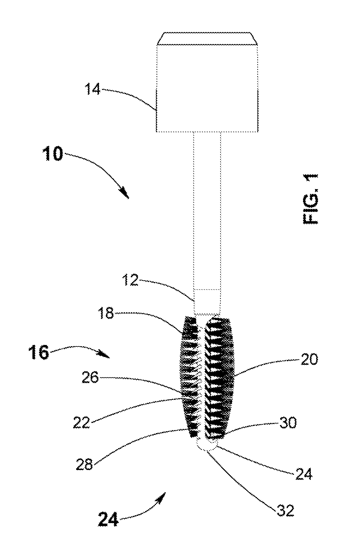
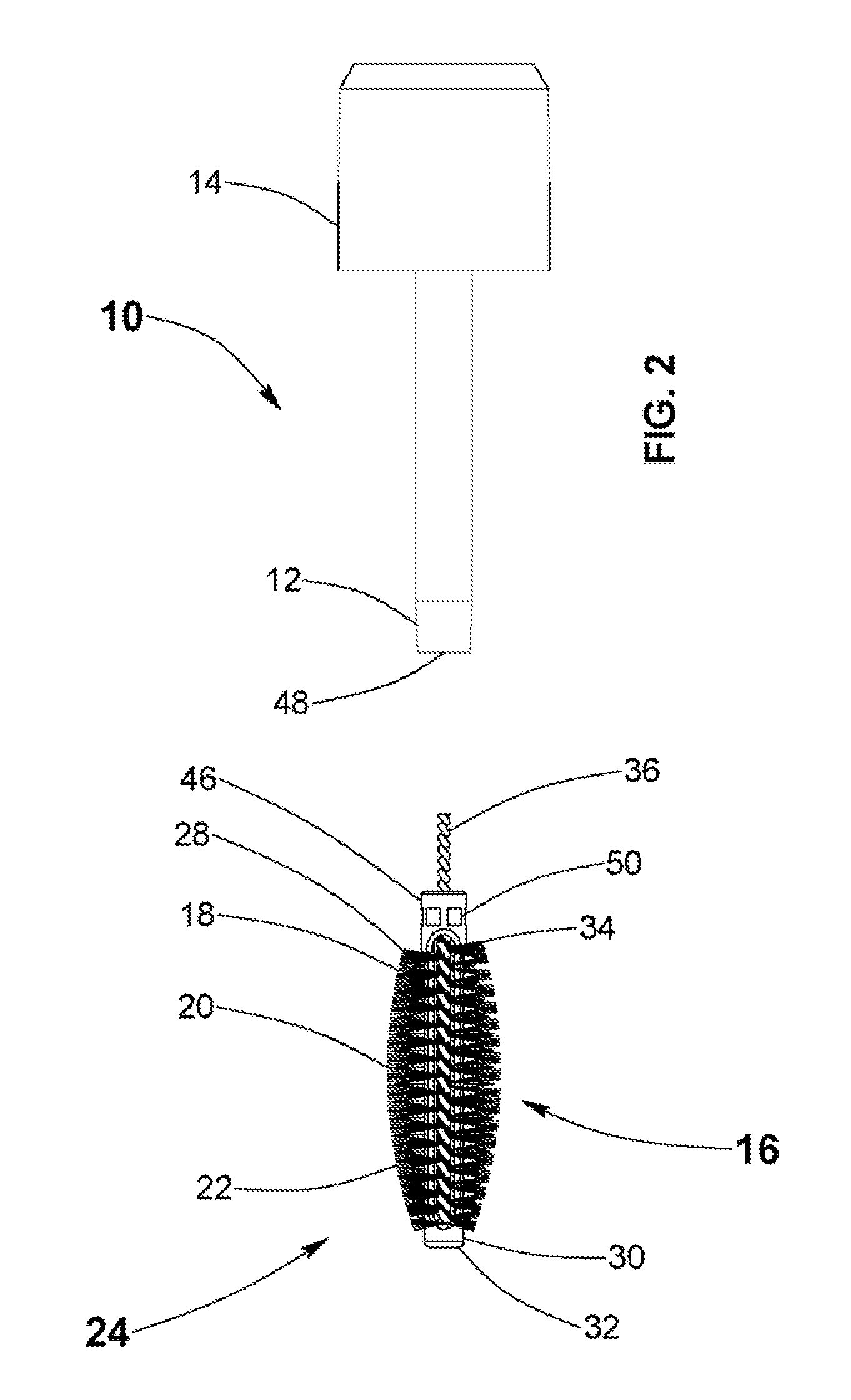
[0017]In carrying forth the aforementioned objects, one embodiment of the invention comprises a cosmetic applicator with disparate material application zones for permitting the achievement of multiple cosmetic material application effects with the applicator. The cosmetic applicator has a wire core formed from first and second wire segments twisted into a helical configuration to form a plurality of coils. A plurality of radially disposed bristles are secured between the first and second wire segments of the wire core to form a brush head for being dipped into a volume of cosmetic material. The bristles of the brush head are disposed in at least first and second distinct bristle zones with the bristles of the first bristle zone being of a first bristle type and the bristles of the second bristle zone being of a second bristle type different than the first bristle type. With this, the first bristle zone can provide a first material application property, and the second bristle zone can provide a second material application property different from the first material application property.

Problems solved by technology

Despite variations in the shape and material composition of the bristles, wire, and the contour of the brush, the cosmetic applicators of the prior art have been substantially limited in their adaptability to different materials and application goals.
Disadvantageously, purchasing multiple separate cosmetic applicators to achieve varied application goals is expensive.
Furthermore, storing and transporting a plurality of cosmetic applicators can be awkward and cumbersome.
Another recognized and long-standing problem with the use of cosmetic applicators is the phenomenon commonly referred to as backwipe.
Consequently, as the cosmetic brush is repeatedly removed and reinserted through the wiper, a reverse wiping action or backwipe occurs thereby producing a buildup of residue on the outer side of the wiper.
The backwiped cosmetic material is inherently messy and unsightly and wastes mascara product while reducing the ease and effectiveness of proper cosmetic application.
This is particularly true as the backwiped product hardens over time thereby hindering use and closure of the cosmetic applicator and causing an undesirable condition referred to as clumping.
Even assuming its effectiveness, arrangements such as that taught by the '185 patent are quite complex in structure and operation.
With that, the cost of manufacture is invariably increased.
Furthermore, the likelihood of malfunction is increased, particularly in the presence of pasty cosmetic materials.

Method used


Image

  • Cosmetic Applicator with Disparate Material Application Zones and Backwipe Return
  • Cosmetic Applicator with Disparate Material Application Zones and Backwipe Return
  • Cosmetic Applicator with Disparate Material Application Zones and Backwipe Return

Examples


Embodiment Construction

[0042]It will be appreciated that the cosmetic applicator with disparate material application zones described herein can pursue widely varied embodiments. However, to ensure that one skilled in the art will be able to understand and, in appropriate cases, practice the present invention, certain preferred embodiments of the broader invention revealed herein are described below and shown in the accompanying drawing figures. Before any particular embodiment of the invention is explained in detail, it must be made clear that the following details of construction, descriptions of geometry, and illustrations of inventive concepts are mere examples of the many possible manifestations of the invention.

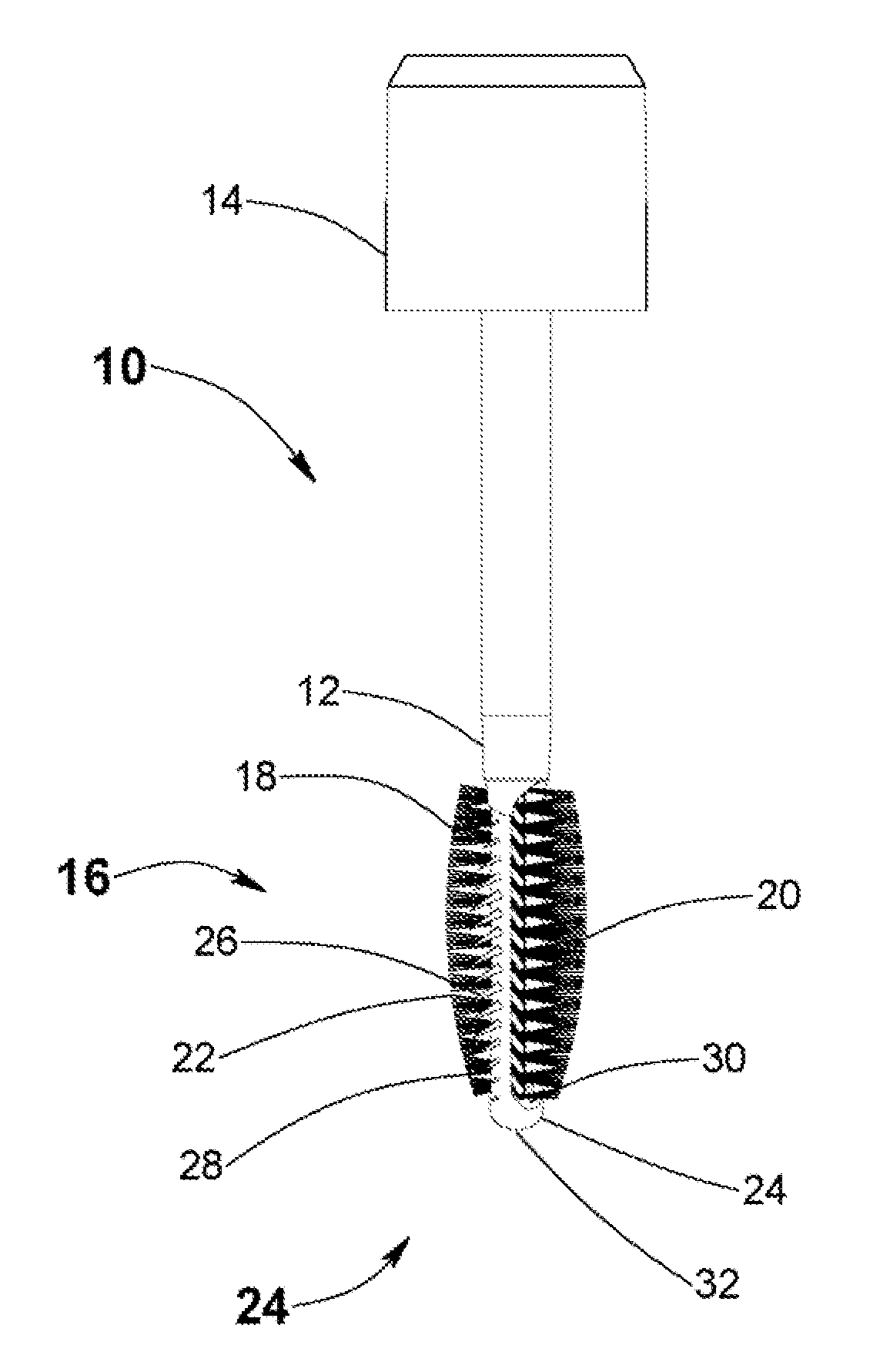
[0043]A manifestation of the present invention for a cosmetic applicator with disparate material application zones is indicated generally at 10 in FIG. 1. There, the cosmetic applicator 10 has an application rod 12 with a proximal end and a distal end. A cap 14, which also acts as a handle dur...


PUM


Abstract

A cosmetic applicator with disparate material application zones and a backwipe return for permitting the achievement of multiple cosmetic material application effects with a single applicator and for permitting the return of backwiped cosmetic material to a cosmetic bottle. The applicator has a wire core formed from first and second wire segments twisted into a helical configuration to form a plurality of coils. A plurality of radially disposed bristles are retained by the wire core to form a brush head. Multiple distinct bristle zones of different bristle types exhibit distinct material application properties in a single cosmetic applicator. Backwiped cosmetic material can be returned to the cosmetic bottle by a sloped shoulder at a proximal end of an applicator rod in combination with a cosmetic material passageway in a sloped facing surface of a flexible inner ring of a wiper.

Description

FIELD OF THE INVENTION[0001]The present invention relates generally to cosmetic applicators. More particularly, disclosed herein is a cosmetic applicator with multiple distinct zones providing multiple, disparate performance characteristics in a single applicator and with a backwipe return arrangement.BACKGROUND OF THE INVENTION[0002]Cosmetic dispensers for mascara and other liquid or pasty cosmetics commonly are founded on two pieces, a container and a cap. The container typically comprises a bottle with an open inner volume for retaining a volume of the cosmetic material. The cap normally has a rod or wand that projects distally therefrom. A brush or other structure capable of retrieving cosmetic from the open inner volume of the bottle and applying the cosmetic to a body surface is retained at the distal end of the wand for being dipped into the volume of cosmetic. When dipped in the cosmetic, the brush becomes loaded with the liquid or pasty material for permitting controlled ap...

Claims


Application Information

Patent Timeline
IPC IPC(8): A45D40/26A46B11/00
CPCA45D40/267A46B3/16A46B2200/1053A46B9/021A46B3/18
Inventor LEGASSIE, RAYMOND P.
Owner HCP PACKAGING USA
Learn More