Gas compression system

a gas compression and gas technology, applied in the direction of liquid transferring devices, liquid fuel engines, borehole/well accessories, etc., can solve the problems of increasing pressure and power, uneven distribution of such matter over the life span of the field, and limited capacity of the compressor, so as to achieve a substantially lower cost and increase pressure

Active Publication Date: 2011-03-03
EQUINOR ENERGY AS
View PDF36 Cites 23 Cited by
  • Summary
  • Abstract
  • Description
  • Claims
  • Application Information

AI Technical Summary

Benefits of technology

[0025]The most essential advantage of the present invention is that liquid and gas is given increased pressure in one and the same unit. Thus, there is no need of conven...

Problems solved by technology

Today, compressors have limited capacity, and the increase in pressure and power are at maximum limited to a few megawatts.
The challenges to be met in this respect are amongst others transfer of large effect volumes below sea level; handling of sand, water, oil/condensate, and gas; together with possible pollution,...

Method used


Image

  • Gas compression system
  • Gas compression system
  • Gas compression system

Examples


Embodiment Construction

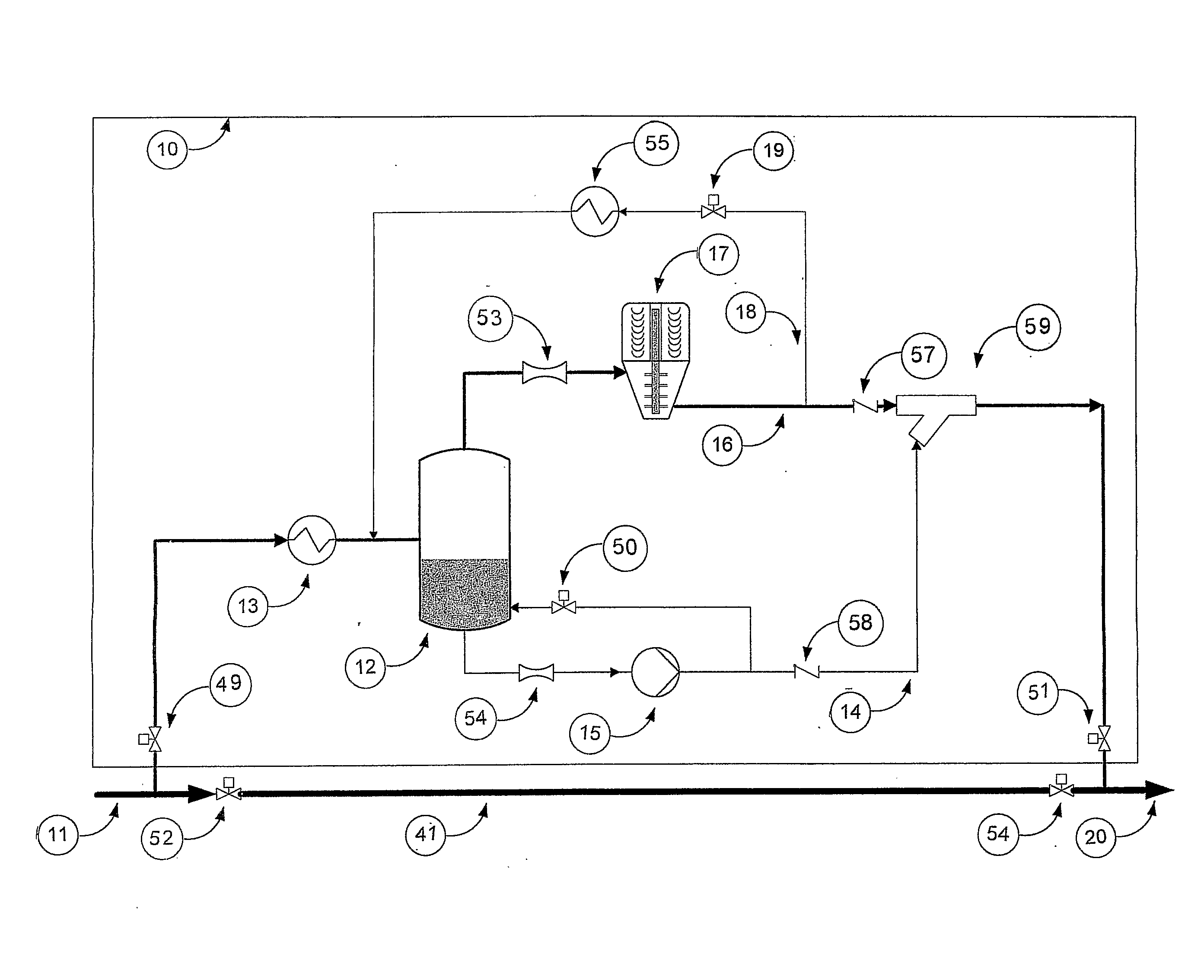
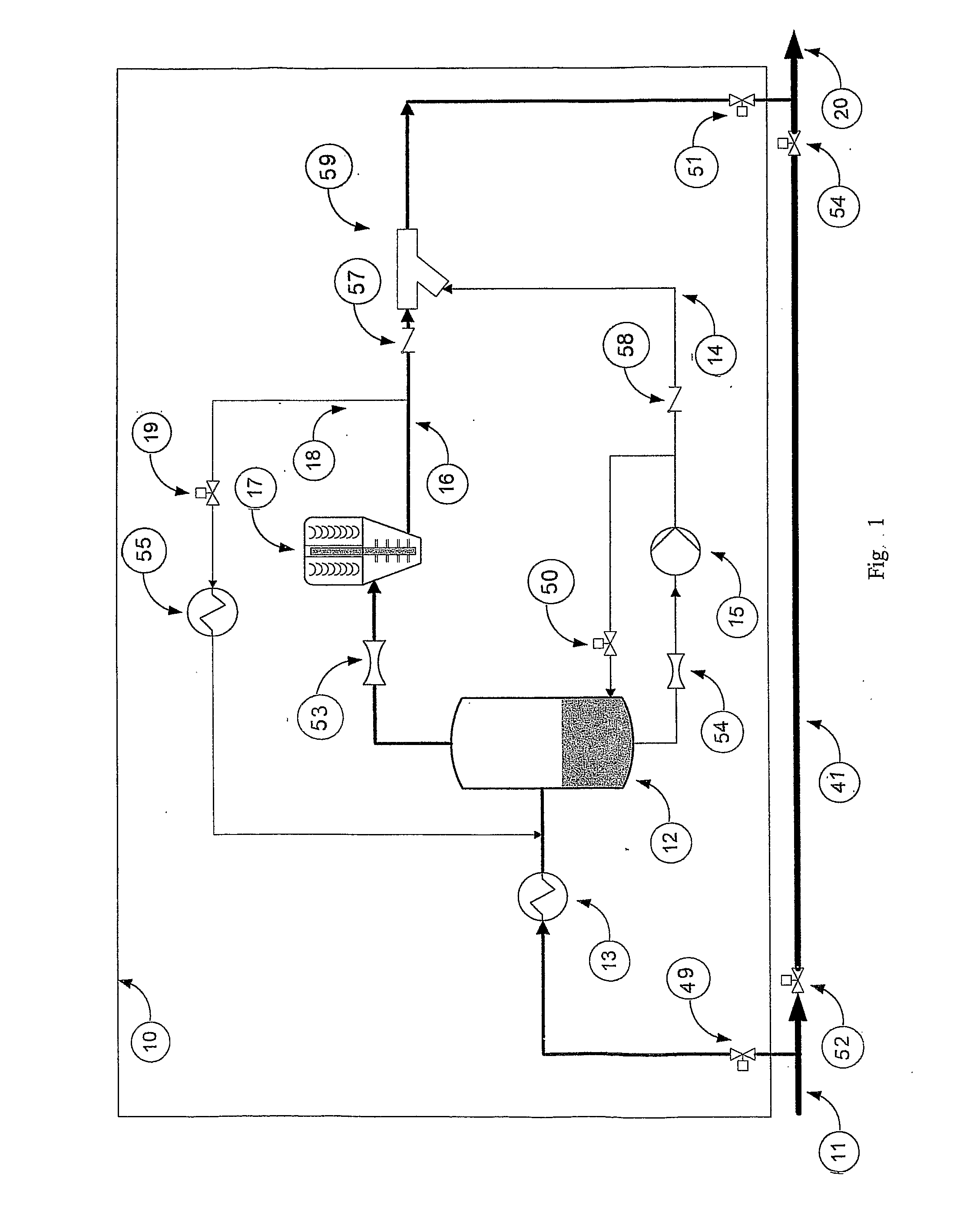
[0035]FIG. 1 shows schematically a system diagram of sub sea compressor system 10 according to a prior art solution. According to the prior art solution the system comprises a supply line 11 where the well flow either may flow naturally due to an excess pressure in the well through the ordinary pipe line 41, when the valves 49 and 51 are closed, while the valves 52 and 54 are open, or through the compressor system when the valves 49 and 51 are open and the valves 52 and 54 are closed.

[0036]When the well flow is fed into the compressor system 10, the well flow is fed to a liquid scrubber or separator 12, where gas and liquid / particles are separated. Up front of the inlet to the liquid separator 12, a cooler 13 is arranged, cooling the well flow down from typically 70° C. to typically 20° C. before the well flow enters the liquid separator 12. The cooler 13 reduces the temperature of the well flow so that liquid is separated out and the portion of liquid is increased. This reduction o...


PUM


Abstract

The invention relates to a wet gas compression system comprising a compact flow conditioner (21), intended to be placed below sea level in close vicinity to a well head or on a dry installation, said flow conditioner (21) being intended to receive a multi-phase flow through a supply pipe (11) from a sub sea well for further transport of such hydrocarbons to a multi-phase receiving plant, and where preferably avoid sand accumulation or remove as much sand as possible from the multi-phase flow, the gas (G) and the liquid (L) being separated in the flow conditioner (21) whereupon the separated gas (G) and liquid (L) are re-assembled and enters a multi-phase meter (46) prior to boosting by means of a compressor (22). In the combined multi-phase pump and compressor unit (22), as an integrated unit, comprises a combined multi-phase pump and compressor unit (22) functioning on the centrifugal principle, used for trans-porting liquid and gas from a flow conditioner (21) to a remote multi-phase receiving plant.

Description

THE TECHNICAL FIELD[0001]The present invention relates to a system for wet gas compression, comprising a compact flow conditioner, a multi-phase flow meter and a downstream multi-phase compressor, preferably of the centrifugal compressor type, designed to be installed below sea level in the vicinity of a well head or on a dry installation, such as a platform or an onshore plant, the flow conditioner being designed to be supplied with multi-phase flow of hydrocarbons from a sub sea well, convey and preferably avoid accumulation or remove as much sand from said multi phase flow as possible.BACKGROUND FOR THE INVENTION[0002]Future sub sea installations will require equipment for increasing the pressure in the well flow in order to achieve optimum exploitation of the reservoir. Use of machines which increases the pressure, contribute to a reduction of the down hole pressure in the well. This will then lead to an accelerating production from the reservoir, providing a possibility for mai...

Claims


Application Information

Patent Timeline
IPC IPC(8): F04F1/00
CPCE21B43/01F04D31/00F04D25/0686E21B43/36Y10T137/2931Y10T137/2036Y10T137/2562Y10T137/3003Y10T137/87265E21B43/35F04D13/12F04D25/16F04D29/58F04D25/06F04D13/06F04D29/284F04D29/22F04D29/70F04D29/40F04D29/046F04D29/05F04F5/04F04D1/00F04D17/08
Inventor BJORGE, TORBRENNE, LARSUNERBAKKE, HARALDEGERDAHL, BJORN-ANDRERAMBERG, RUNE MODEBAKKE, WILLIAM
Owner EQUINOR ENERGY AS
Why Eureka
Try Eureka