Well seals

a well and seal technology, applied in the field of well seals, can solve the problems of affecting the sealing effect of the well, etc., and achieve the effect of restricting the ambiguity

Active Publication Date: 2011-03-03
DEN NORSKE STATS OLJESELSKAP AS
View PDF2 Cites 13 Cited by
  • Summary
  • Abstract
  • Description
  • Claims
  • Application Information

AI Technical Summary

Benefits of technology

[0032]Typically, at least two wellbore tools are run in the first and/or second well

Problems solved by technology

Candidate wells for such operations often lack the necessary certification and/or the required annular barriers.
Such operations ca

Method used


Image

  • Well seals
  • Well seals
  • Well seals

Examples


Embodiment Construction

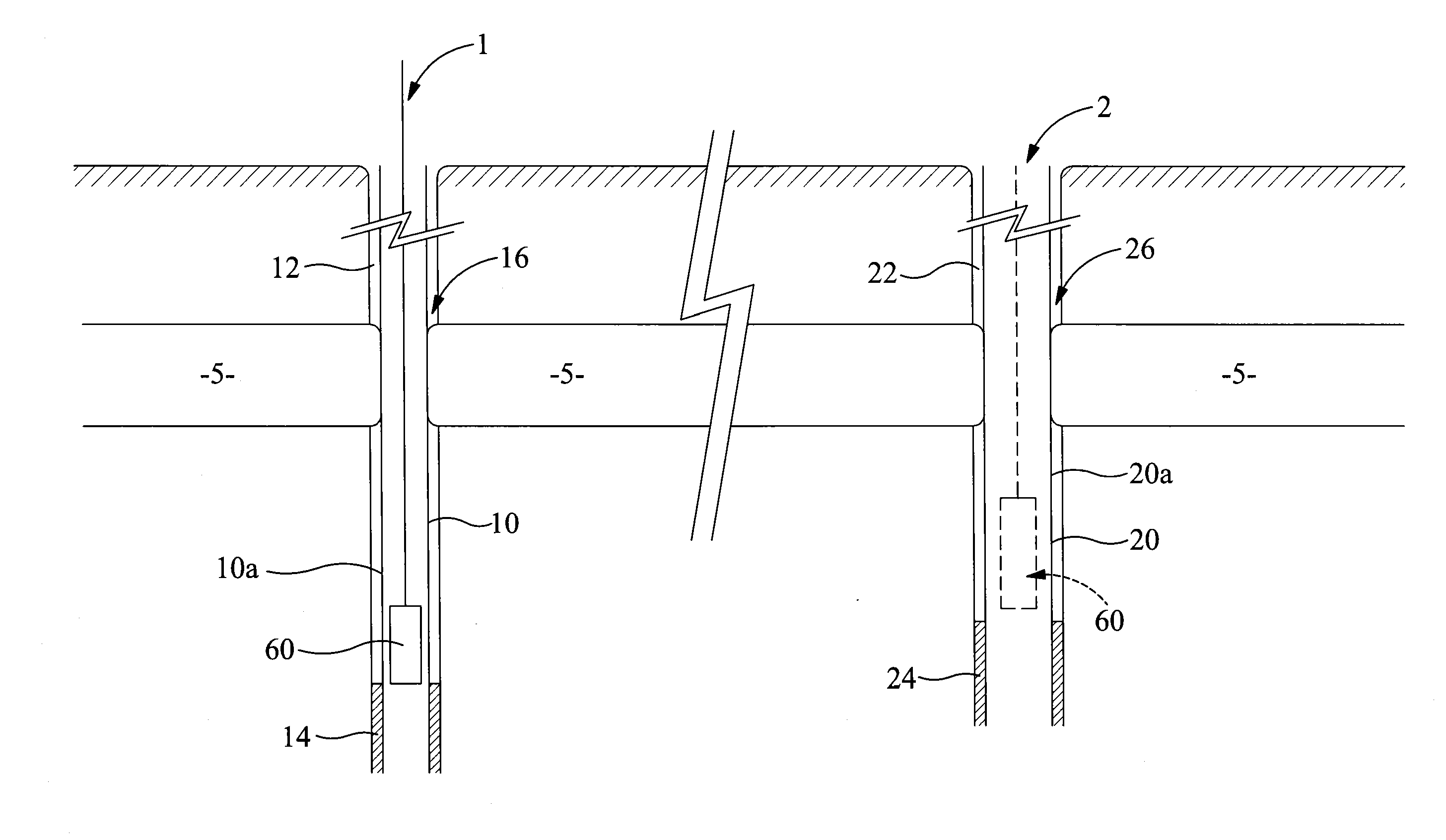
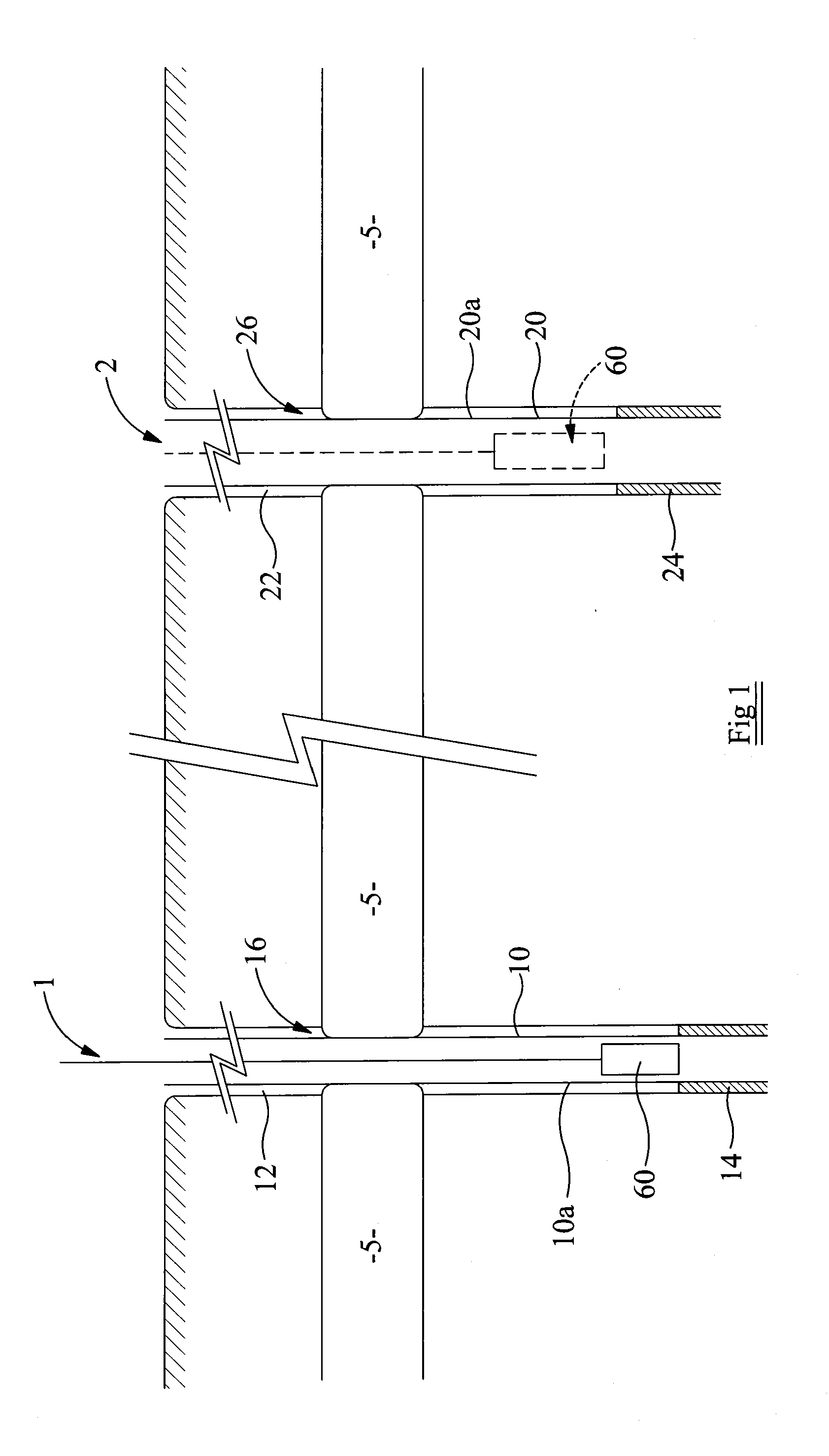
[0040]With reference firstly to FIG. 1, two well bores 1, 2 in different locations are shown extending from the earth's surface through a geological formation in the form of a shale formation 5 which has undergone lateral creep. The well bores 1, 2 are lined with casing sections 10, 20 defining annular spaces or casing annuli 12, 22 defined between outer surfaces 10a, 20a of the casing sections and walls of the wellbores 1, 2. In lower regions 14, 24 of the wellbores 1, 2, the casing sections are cemented in place, but above in regions 16, 26, cementation is incomplete to the extent that the cement itself does not provide the necessary sealing of the wellbore annuli 12, 22 for abandonment of the well track or for conducting a side track operation.

[0041]In this case, the shale formation 5 has crept laterally due to natural causes over time and is shown, in FIG. 1, in abutment with the casing sections 10, 20 in the regions 16, 26 of the casing annuli where there is no cement. The foll...


PUM


Abstract

A method for determining integrity of annular seals in wellbores. In an embodiment, two wellbores are selected that extend through a common geological formation which is capable of sealing against casing sections located in the wellbores. A pressure test is typically carried out in a first of the wellbores to check that the formation provides an effective seal, and a logging tool is typically run to obtain well log data from which can be derived a characteristic response that is associated with the formation providing an effective annular seal around the casing section in the first wellbore. A logging tool may then be run in the second of the wellbores to obtain a second set of well log data, which are comparable with the characteristic response to determine whether the formation provides an effective annular seal in the second wellbore.

Description

RELATED APPLICATION[0001]The present application claims priority to GB Application No. 0915010.3 filed Aug. 28, 2009, which is incorporated herein in its entirety by reference.TECHNICAL FIELD[0002]The present invention relates to well seals, and in particular, but not exclusively, to a method of determining integrity of an annular seal in a wellbore. In particular embodiments, it relates to well seals in well tubular annuli and to identifying and qualifying such seals as an effective annular barrier.BACKGROUND ART[0003]In various circumstances, wells that have been drilled into the earth need to be sealed off to prevent escape of well fluids upward through the well and well annulus to the earth's surface into the sea or into another geological layer. This can be particularly important in a “sidetrack” drilling operation where a drill string is run into a pre-existing cased wellbore and is used to drill a new sidetrack wellbore through the casing wall of a pre-existing wellbore to ac...

Claims


Application Information

Patent Timeline
IPC IPC(8): E21B47/00E21B47/06E21B47/12E21B47/10
CPCE21B33/10E21B47/1025E21B47/00E21B47/117
Inventor WILLIAMS, STEPHEN MARKCARLSEN, TRULSCONSTABLE, KEVIN
Owner DEN NORSKE STATS OLJESELSKAP AS
Why Eureka
Try Eureka