Robust potentiometric sensor

a potentiometer and sensor technology, applied in the field of electrochemical sensors, can solve the problems of not providing fluid/solution ground contact, relatively expensive, and generally incompatible with applications requiring the use of non-metallic components

Inactive Publication Date: 2011-03-03
INVENSYS SYST INC
View PDF28 Cites 38 Cited by
  • Summary
  • Abstract
  • Description
  • Claims
  • Application Information

AI Technical Summary

Problems solved by technology

Furthermore—and especially for process analytical applications—the sensor is often required to operate in harsh chemical environments over a wide range of temperatures and pressures and in the presence of shock, vibration, electrical currents in the test fluid, and electromagnetic radiation.
As one example of such a compromise, the Ceragel CPS71 series of 12-mm pH probes commercially available from Endress+Hauser of Switzerland, does not provide a fluid / solution ground contact.
This approach is typical of many conventional combination probes, and tends to be relatively expensive while restricting the ability to modify the configuration for alternate sizes.
This approach, however, is generally incompatible with applications requiring the use of non-metallic components.
A drawback of this approach, however, is that the time response of the temperature sensor to changes in process fluid temperature tends to be compromised by the thermal mass of the combination pH probe.
This approach tends to suffer the same drawback as Makabe with regard to the response time of the temperature sensor.
In addition, placement of the solution ground contact in the electrolyte tends to be limiting.

Method used


Image

  • Robust potentiometric sensor
  • Robust potentiometric sensor
  • Robust potentiometric sensor

Examples


example 1

Robustness against Sterilization

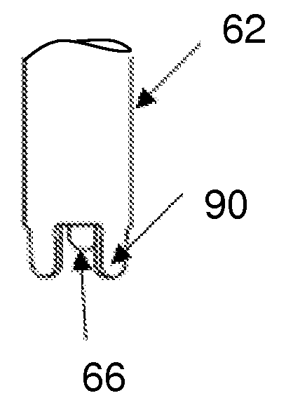
[0056]An electrode 60 (FIG. 3) was fabricated with a domed pH glass membrane 66, a 12 mm diameter PEEK housing 62, Viton® seals 82, 84, a liquid junction assembly 114 including a ceramic rod within a PEEK sleeve, a Kynar® RTD / solution ground end cap 78, a PFA pressure equalization bladder 86, and a NAFION® ion-barrier inner reference assembly 70.

[0057]FIG. 9 shows the test results of the pH sensor of Example 1 after multiple 30-minute autoclave cycles (steam-sterilizations) at 125° C. Slope between pH 4 and 7 buffers remained above 90% of theoretical (Nernst) after 60 cycles. 80% slope was chosen as benchmark for acceptable performance.

example 2

Operation at Process Pressure of 150 psi

[0058]An electrode 60 was fabricated substantially as in Example 1, but with the 12 mm diameter housing 62 fabricated from Pyrex® glass instead of PEEK.

[0059]FIG. 10 shows the response of the pH sensor of Example 2 in pH 4, 7, and 10 buffers under a process pressure of 150 psi. No physical damage nor abnormal response behavior was observed.

example 3

Operation at elevated Temperature and Pressure

[0060]FIG. 11 shows the output of a probe configured as in Example 2 in pH 4 buffer at a temperature of 121° C. pressure of 150 psi. The output shown indicates successful operation.


PUM

PropertyMeasurementUnit
diameteraaaaaaaaaa
pore sizesaaaaaaaaaa

Abstract

A modular potentiometric sensor includes a housing having measuring and reference half-cells, a temperature sensor, and solution ground combination assembly. An electrical conductor of the combination assembly extends through the housing, while remaining electrically isolated from the housing and half-cells, terminating at an electrically and thermally conductive end cap. Seals at opposite ends of the housing permit portions of the half-cells and the combination assembly to extend therethrough. The seals, measuring half-cell, and the combination assembly define an electrolyte compartment for the reference half-cell. The end cap provides close thermal coupling to the test fluid while also serving as a test fluid ground that is electrically isolated from the electrolyte compartment. The housing, measuring half-cell, reference half-cell, and combination assembly are modular, with the measurement sensor configurable in a plurality of lengths by altering the length of the housing independently of the half-cells and combination assembly.

Description

RELATED APPLICATION[0001]This application claims the benefit of U.S. Provisional Patent Application Ser. No. 61 / 239,274, entitled Robust pH Sensor, filed on Sep. 2, 2009, the contents of which are incorporated herein by reference in their entirety for all purposes.BACKGROUND OF THE INVENTION[0002](1) Field of the Invention[0003]The present invention generally relates to electrochemical sensors and more particularly to sensor assemblies including both sensing and reference half-cells in a single robust configuration.[0004](2) Background Information[0005]Electrochemical potential measurements are commonly used to determine solution pH, other selective ion activities, ratios of oxidation and reduction activities, as well as other solution characteristics. A pH / ion selective electrode / oxidation reduction potential meter (hereafter referred to as a pH / ISE / ORP meter) is typically a modified voltmeter that measures the electrochemical potential between a reference half-cell (of known poten...

Claims


Application Information

Patent Timeline
Patent Type & Authority Applications(United States)
IPC IPC(8): G01N27/30G01N27/333G01N27/26B23P11/00
CPCY10T29/49826G01N27/4035
Inventor BOWER, MICHAEL M.FOURNIER, DAVID G.SUN, ZHISHENGTALUTIS, STEPHEN B.TOWER, DANIEL G.WEST, STEVEN J.
Owner INVENSYS SYST INC
Why Eureka
Try Eureka