Boundary acoustic wave device

Active Publication Date: 2011-03-03
MURATA MFG CO LTD
View PDF4 Cites 32 Cited by
  • Summary
  • Abstract
  • Description
  • Claims
  • Application Information

AI Technical Summary

Benefits of technology

[0021]In the boundary acoustic wave device according to various preferred embodiments of the present invention, the higher-order mode boundary acoustic wave at an anti-resonance point has an acoustic velocity Va greater than the acoustic velocity V1 of the fast transverse bulk wave of the piezoelectric substrate. Accordingly, higher-order mode spurious responses are effectively prevented. Since higher-order mode spurious responses can be prevented without reducing the thickness of the material of the first m

Problems solved by technology

However, in the boundary acoustic wave device having the three-media structure disclosed in WO 98/52279, higher-order mode spurious responses often occur.
Unfortunately, if the thick

Method used


Image

  • Boundary acoustic wave device
  • Boundary acoustic wave device
  • Boundary acoustic wave device

Examples


first experimental example

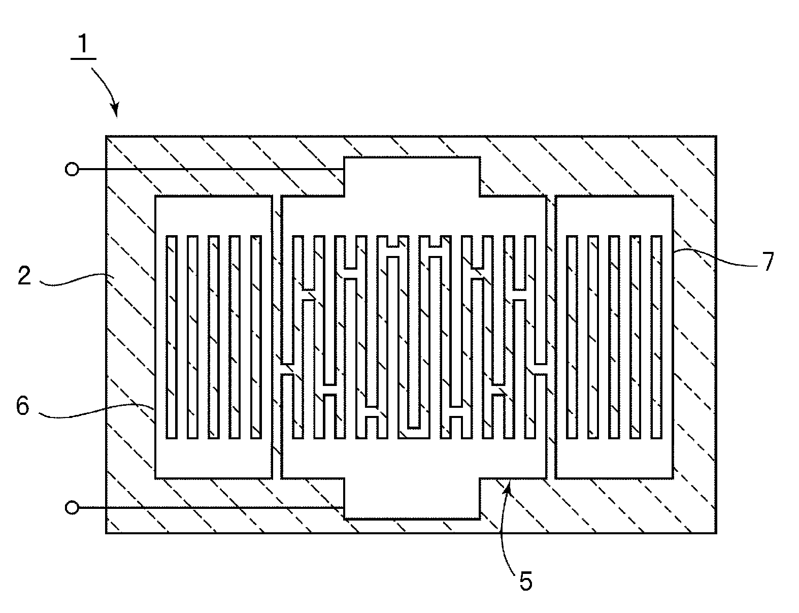
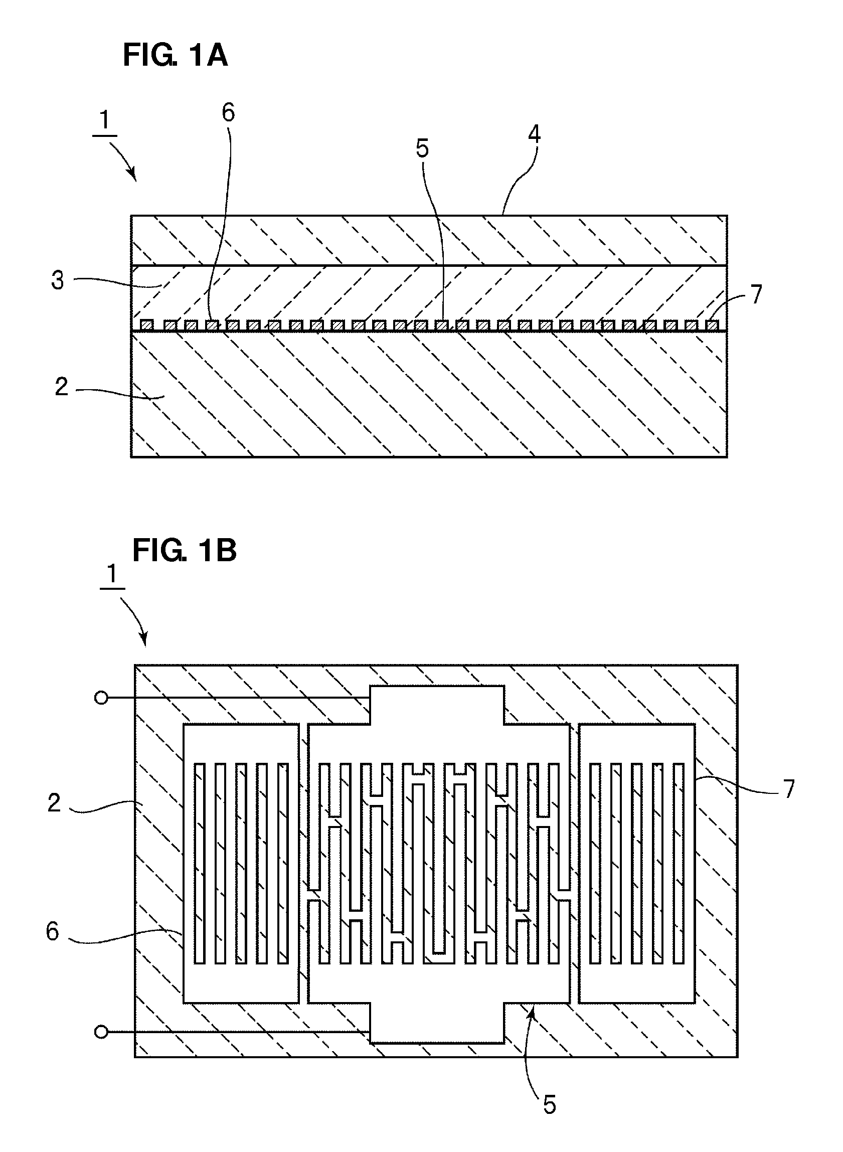
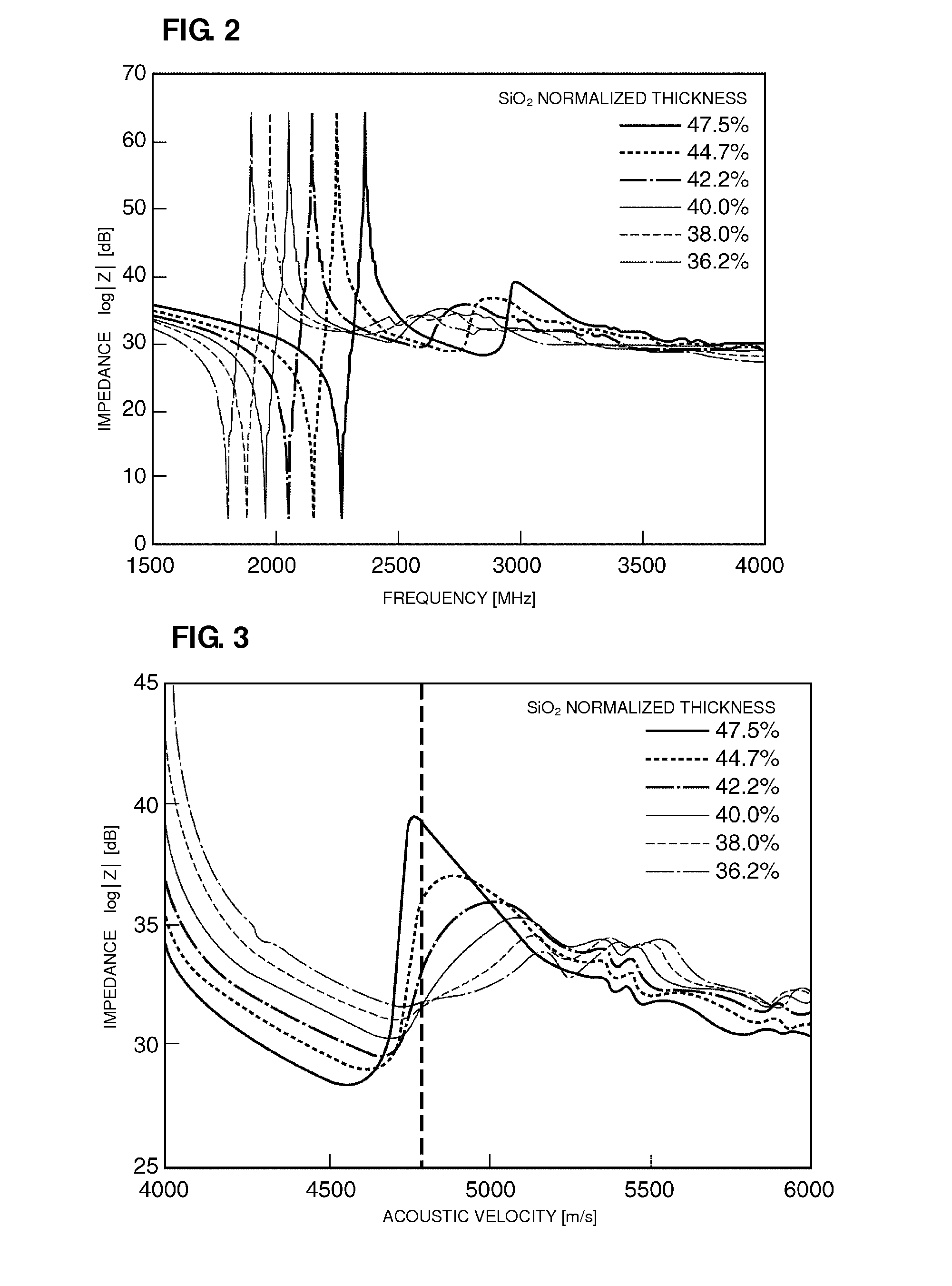
[0044]FIG. 2 is a plot showing the impedance characteristics of the boundary acoustic wave device 1 when the normalized thickness of the SiO2 first medium layer 3 is, for example, about 47.5%, about 44.7%, about 42.2%, about 40.0%, about 38.0% or about 36.2%. The piezoelectric substrate 2 of the boundary acoustic wave device 1 was made of LiNbO3 single crystal having a crystal orientation expressed by Euler angles (0°, 105°,0°). The electrode structure including the IDT electrode 5 included a multilayer metal film formed by depositing a Pt layer, an Al layer and a Pt layer in that order. The normalized thicknesses of the Pt, Al and Pt layers were about 1.1%, about 8.6 and about 1.1%, respectively. The number of fingers of the IDT electrode 5 was 60, and the duty ratio was about 0.5. The wavelengths λ of the boundary waves corresponding to the SiO2 normalized thicknesses were about 1.6 μm, about 1.7 μm, about 1.8 μm, about 1.9 μm, about 2.0 μm, and about 2.1 μm, respectively. The num...

second experimental examples

[0055]A plurality of boundary acoustic wave devices were prepared in substantially the same manner as in the first experimental example except that the duties of the respective IDT electrodes 5 were set to about 0.4, about 0.45, about 0.5, about 0.55 and about 0.6. FIG. 5 shows the phase characteristics in a higher order mode of these boundary acoustic wave devices.

[0056]As shown in FIG. 5, when the duty is about 0.6, the higher-order mode acoustic velocity Va at an anti-resonance point is about 4750 m / s. On the other hand, when the duty is about 0.4, the higher-order mode acoustic velocity Va at an anti-resonance point should be about 4860 m / s. However, the anti-resonance point around 4860 m / s is not clear. This is because the higher-order mode is leaked to the LiNbO3 layer by an increased higher-order mode acoustic velocity. It is therefore shown that when the duty is about 0.4, the highest phase is as low as very−40° in the vicinity of an acoustic velocity of about 4750 m / s, that...

third experimental example

[0057]Electrodes including the IDT electrode 5 were formed by depositing a Pt layer, an Al layer, and a Pt layer in that order from the piezoelectric substrate 2 side for a Pt / Al / Pt multilayer metal film. In the multilayer metal film, the normalized thickness of the Al layer was set to about 8.6%, and the normalized thickness of the Pt layer at the first medium layer 3 side was changed to about 2.2%, about 1.65%, about 1.1%, about 0.55%, or 0% while the sum of the normalized thicknesses of the Pt layers was maintained constant or substantially constant. The sum of the normalized thicknesses of the Pt layers was about 2.2%.

[0058]FIG. 6 shows the relationship between the acoustic velocity and the phase of a plurality of boundary acoustic wave devices having the electrode structures described above.

[0059]As shown in FIG. 6, the higher order mode acoustic velocity Va at the anti-resonance point is greater than about 4750 m / s and the highest phase is low in each case shown in FIG. 6. Thu...


PUM


Abstract

A boundary acoustic wave device includes a first medium layer made of a first dielectric material and a second medium layer made of a second dielectric material having an acoustic velocity different from the acoustic velocity of the first dielectric material. The first medium layer and the second medium layer are disposed on a piezoelectric substrate, and an IDT electrode is arranged along the interface between the piezoelectric substrate and the first medium layer. When the fast transverse bulk wave of the piezoelectric substrate has an acoustic velocity V1 and a higher-order mode boundary acoustic wave has an acoustic velocity Va at an anti-resonance point, the boundary acoustic wave device satisfies the relationship Va>V1.

Description

BACKGROUND OF THE INVENTION[0001]1. Field of the Invention[0002]The present invention relates to boundary acoustic wave devices using boundary acoustic waves propagating along an interface between a piezoelectric substrate and a dielectric layer, and more particularly, to a boundary acoustic wave device having a three-media structure including a second medium layer made of a first dielectric material disposed on a first medium layer made of a second dielectric material.[0003]2. Description of the Related Art[0004]Boundary acoustic wave devices have recently received significant attention as an alternative to surface acoustic wave devices. Boundary acoustic wave devices do not require hollow packages. Accordingly, the size of resonators and filters can be significantly reduced by using boundary acoustic wave devices.[0005]WO 98 / 52279 discloses a boundary acoustic wave device having a three-layer structure including a first medium layer and a second medium layer disposed on a piezoele...

Claims


Application Information

Patent Timeline
IPC IPC(8): H01L41/04
CPCH03H9/0222H03H9/14541H03H9/6423H03H9/1452
Inventor YAMANE, TAKASHI
Owner MURATA MFG CO LTD
Why Eureka
Try Eureka