
Method And System For Limiting Interference In Magnetometer Fields

a magnetometer field and interference limitation technology, applied in the field of magnetometer-based systems, can solve the problems of respiratory characteristics derived from the determined anatomical displacement, inaccurate measurement of the magnetometer field, and inability to monitor so as to achieve the effect of limiting interference in the magnetometer field and improving the monitoring of the respiratory characteristics of subjects

Inactive Publication Date: 2011-03-03
ADIDAS
View PDF58 Cites 23 Cited by
  • Summary
  • Abstract
  • Description
  • Claims
  • Application Information

AI Technical Summary

Benefits of technology

[0019]The present invention provides apparatuses and methods for improved monitoring of a subject's respiratory characteristics, which is of particular use in the fields of athletic performance monitoring and medical evaluation. A method for limiting interference in magnetometer fields, in accordance with one embodiment of the invention, generally includes providing a magnetometer system having paired first and second magnetometers, the first magnetometer being adapted to generate an external magnetic field, the second magnetometer being adapted to receive and monitor the magnetic field, the second magnetometer being further adapted to generate at least one magnetometer signal representing a change in the magnetic field, and transmitting the magnetic field with a characteristic that varies over time.

Problems solved by technology

Such sources and apparatuses are, however, susceptible to electromagnetic interference from periodic environmental sources (e.g., electrical power lines) that have a frequency synchronous with or sub-harmonic of the magnetic field frequency.
The spurious interference can, and in many instances will, result in inaccurate measurements of the magnetometer field.
Anatomical displacements determined from inaccurate magnetic field measurements (e.g., signals reflecting anatomical displacements) and, hence, respiratory characteristics derived from the determined anatomical displacements can, thus, be in error.
Although the noted conventional systems and techniques successfully limit interference in low to mid-noise environments, magnetometers employing the noted systems and techniques are still susceptible to interference from signal frequencies and harmonics that are close to the magnetic field frequencies.
Although the noted systems and techniques successfully limit interference in a drive signal, the systems and techniques are limited to flux-gate magnetometers.
The noted systems and techniques would thus be ineffective in reducing electromagnetic interference in received magnetic fields and, hence, the effects of such interference on magnetic field transmission measurements.

Method used


Image

  • Method And System For Limiting Interference In Magnetometer Fields
  • Method And System For Limiting Interference In Magnetometer Fields
  • Method And System For Limiting Interference In Magnetometer Fields

Examples


example 1

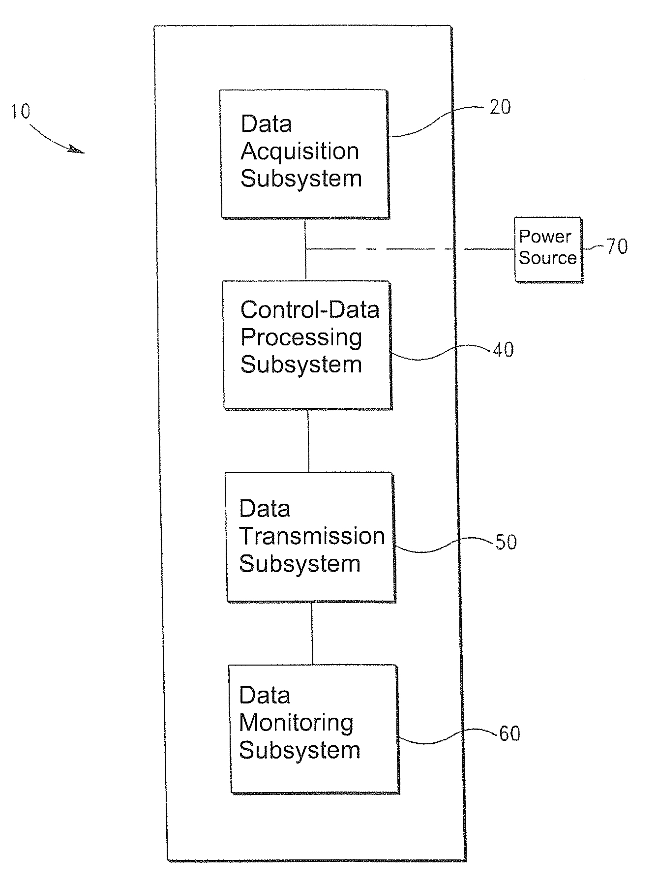
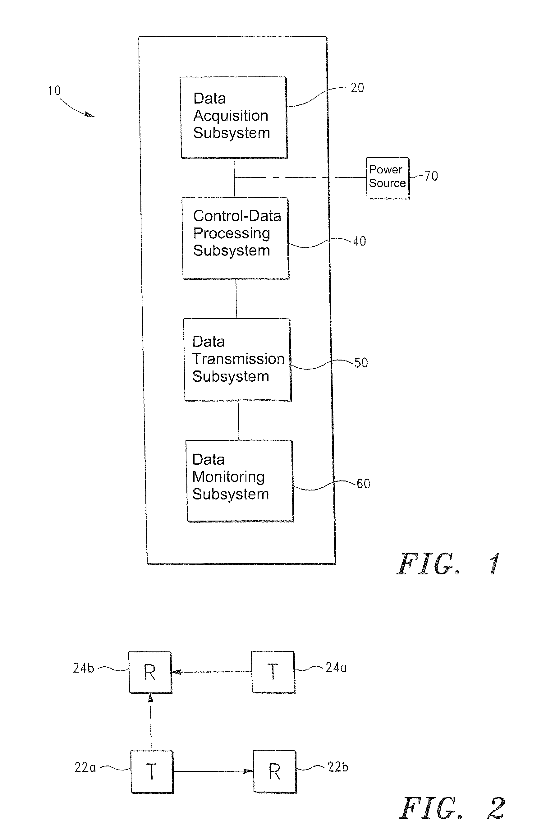
[0088]A physiology monitoring system, such as that illustrated in FIG. 1, is provided.

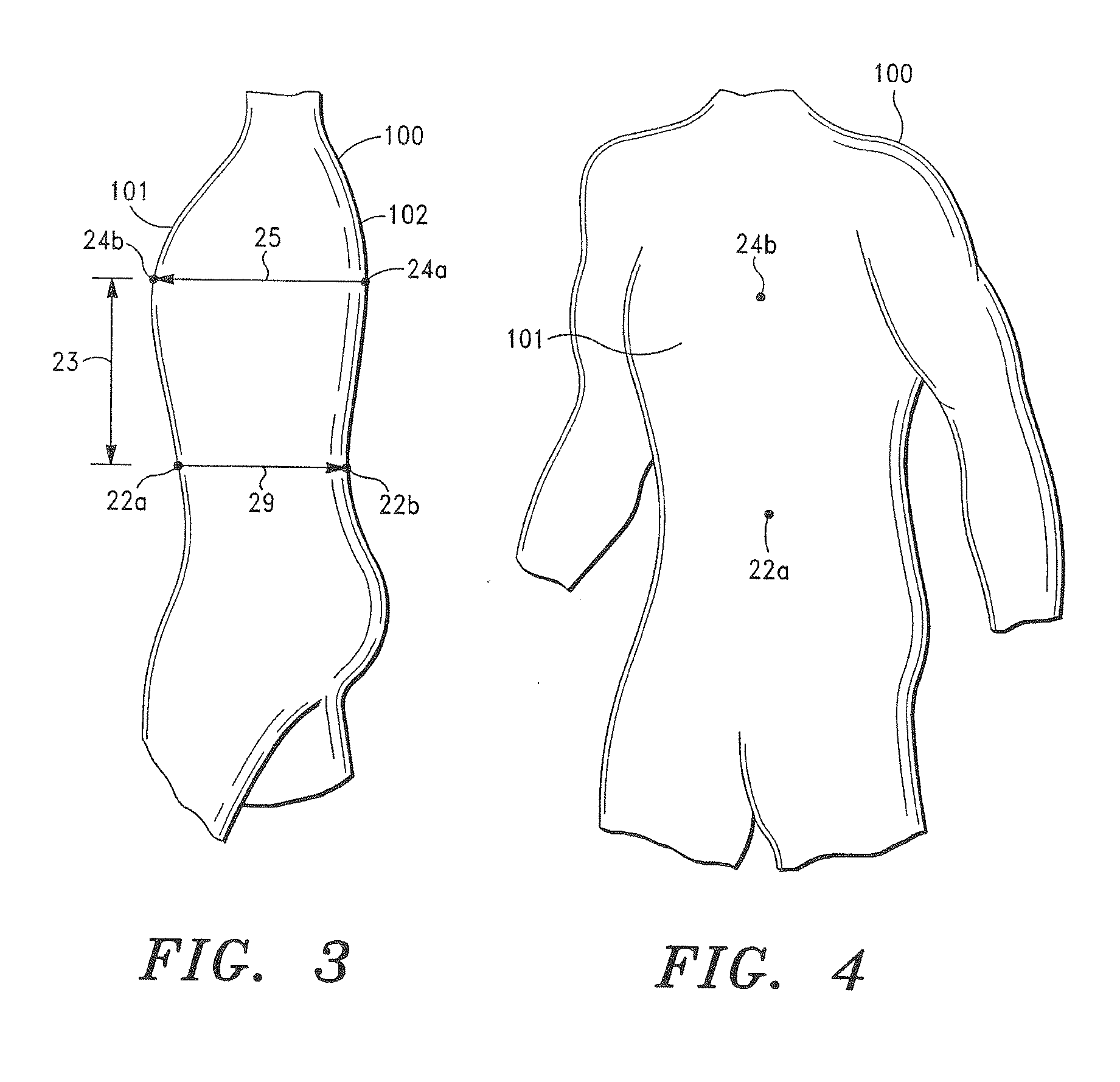
[0089]Paired magnetometers 22a, 22b, and 24a, 24b are positioned on a subject, as shown in FIGS. 3-5 above.

[0090]The magnetic field between one of the magnetometer pairs (e.g., magnetometers 22a, 22b) has a steady state frequency of approximately 9000 Hz. The magnetic field between the other pair of magnetometers (e.g., magnetometers 24a, 24b) has a steady state frequency of approximately 8760 Hz.

[0091]Disposed close to the monitored subject is a fluorescent light generating a signal having frequencies in the range of 8800 to 9000 Hz. Interference resulting from the fluorescent light signal is detected in the magnetic field between magnetometers 22a and 22b and, hence, in signals representing measured changes in the magnetic field.

[0092]The frequency of the magnetic fields between the paired magnetometers 22a-22b and 24a-24b is then randomly varied between 8900 and 9100 Hz and 8660 and 8860 Hz, res...

example 2

[0093]In example 2, the same physiological monitoring system is employed and the same conditions are present. However, in example 2, the frequency period of the magnetic fields between the paired magnetometers 22a-22b and 24a-24b is pseudo-randomly varied between 1 / 8900 and 1 / 9100 seconds and 1 / 8660 and 1 / 8860 seconds, respectively. Interference by the fluorescent light signal is similarly minimized.

[0094]The methods and systems of the invention, described above, thus provide numerous significant advantages over conventional methods and systems for limiting magnetometer interference. Among the advantages are (i) enhanced reduction of electromagnetic interference in measured magnetic fields, (ii) enhanced accuracy of measured changes in magnetic fields, and, hence, signals representing same, and (iii) detection of very small magnetic fields and changes thereto in high noise environments.

[0095]A further significant advantage is the accurate determination of anatomical and physiologica...


PUM


Abstract

Magnetometer systems, and associated methods, are provided including a first magnetometer adapted to generate an external magnetic field having a characteristic that is varied over time, and a second magnetometer adapted to receive the magnetic field and generate at least one magnetometer signal representing a change in the magnetic field. In one embodiment, the magnetic field characteristic includes the frequency of the generated magnetic field. In another embodiment, the magnetic field characteristic includes the frequency period of the magnetic field.

Description

CROSS-REFERENCE TO RELATED APPLICATIONS[0001]This non-provisional application claims priority to U.S. Provisional Application No. 61 / 275,576, filed on Sep. 1, 2009, which is incorporated herein by reference in its entirety.FIELD OF THE INVENTION[0002]The present invention relates generally to magnetometer-based systems for monitoring anatomical and physiological parameters of a subject. More particularly, the invention relates to methods and systems for limiting electromagnetic interference in magnetometer fields and the resultant degradation in quality of signals reflecting changes in the magnetometer fields.BACKGROUND OF THE INVENTION[0003]In medical diagnosis and treatment of a subject, it is often desirable to assess one or more physiological or performance characteristics or symptoms associated with the subject. Athletic performance and progress are often evaluated by examining changes in physiological and / or performance characteristics. Respiratory air volume and other respira...

Claims


Application Information

Patent Timeline
Patent Type & Authority Applications(United States)
IPC IPC(8): G01R33/02
CPCA61B5/091G01R33/02A61B5/1135
Inventor STONE, ROBERT THOMAS
Owner ADIDAS
Learn More