Image display apparatus and head mounted display

Inactive Publication Date: 2011-03-03
SONY CORP
View PDF10 Cites 47 Cited by
  • Summary
  • Abstract
  • Description
  • Claims
  • Application Information

AI Technical Summary

Benefits of technology

[0021]In the image display apparatus according to the embodiment of the invention or in the image display apparatus in the head mounted display according to the first embodiment of the invention, an assembly of at least the image forming device and the supporting member has the center of gravity at a position apart from the pivoting central axis of the supporting member, and at least the image forming device is pivoted with respect to the optical device by gravity, whereby the image forming device is horizontally held. Further, in the head mounted display according to the second embodiment of the invention, an assembly of the image forming device and the supporting member has the center of gravity at a positi

Problems solved by technology

Meanwhile, the technique disclosed in Japanese Unexamined Patent Application Publication 2000-312319 has need for rotation transmission mechanisms such as an attitude sen

Method used


Image

  • Image display apparatus and head mounted display
  • Image display apparatus and head mounted display
  • Image display apparatus and head mounted display

Examples


example 1

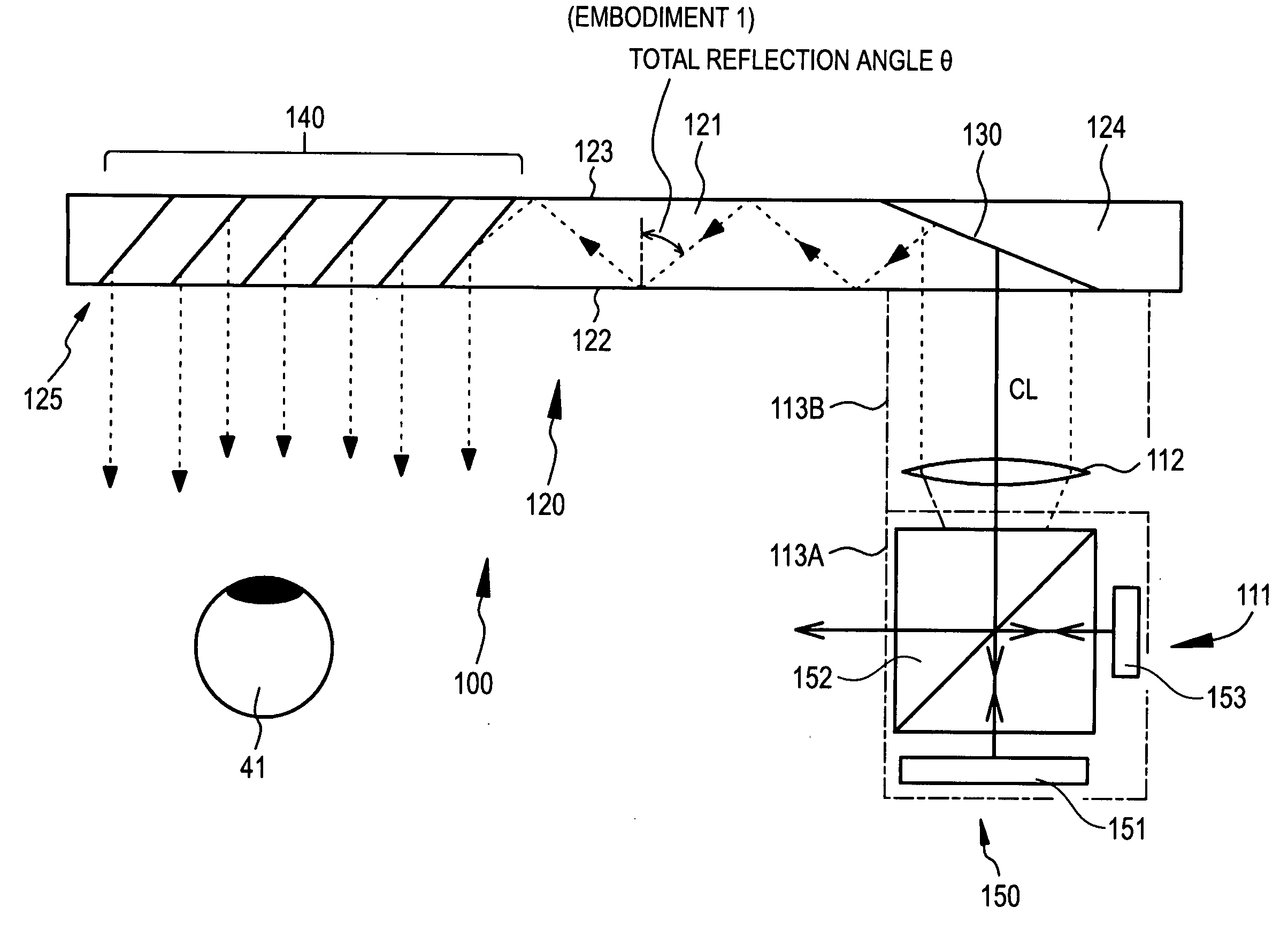
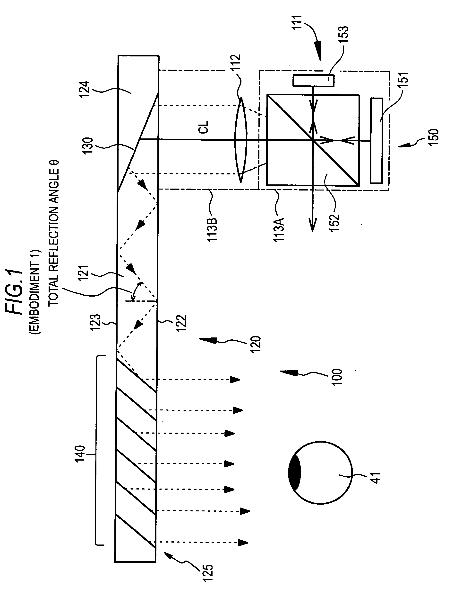
[0080]Example 1 relates to an image display apparatus according to the embodiment of the invention, and a head mounted display according to the first embodiment of the invention. A conceptual diagram of the image display apparatus of Example 1 is shown in FIG. 1, the propagation of light in a light guide plate that forms the image display apparatus of Example 1 is schematically shown in FIG. 2A, and a conceptual diagram showing an arrangement state of the light guide plate, etc. that forms the image display apparatus of Example 1 is shown in FIG. 2B. Further, a schematic view when the head mounted display of Example 1 is viewed from above is shown in FIG. 3, and a schematic view when the head mounted display is viewed from the side is shown in FIG. 4.

[0081]In Example 1 or Embodiments 2 to 7 that will be described below, an image display apparatus 100, 200, 300, or 400 includes:

[0082](A) an image forming device 111 or 211;

[0083](B) an optical system (parallel light emitting optical s...

example 2

[0106]Example 2 is a modification of Example 1. FIG. 5 is a conceptual view of an image display apparatus 200 in a head mounted display according to Example 2. As shown in FIG. 5, an image forming device 211 in Example 2 is formed by an image forming device having a second configuration. That is, the image forming device includes a light source 251, and a scanning member 253 that scans the parallel light emitted from the light source 251. More specifically, the image forming device 211 includes:

[0107](a) a light source 251;

[0108](b) a collimating optical system 252 that converts light emitted from the light source 251 into parallel light;

[0109](c) a scanning member 253 that scans the parallel light emitted from the collimating optical system 252; and

[0110](d) a relay optical system 254 that relays and emits the parallel light scanned by the scanning member 253. The light source 251, the collimating optical system 252, and the scanning member 253 are stored in a housing 213A (shown b...

example 3

[0113]Example 3 is also a modification of Example 1. FIG. 6A is a conceptual view of an image display apparatus 300 in a head mounted display according to Example 3. FIG. 6B is an enlarged schematic sectional view of a part of a reflective volume hologram diffraction grating. In Example 3, an image forming device 110 is formed by an image forming device having a first configuration, similarly to Example 1. An optical device 320 has the same basic configuration and structure as those of the optical device 120 of Example 1 except in configurations and structures of a first deflecting member and a second deflecting member.

[0114]In Example 3, the first deflecting member and the second deflecting member are disposed on a surface of the light guide plate 321 (concretely, a second surface 323 of the light guide plate 321). The first deflecting member diffracts light incident on the light guide plate 321, and the second deflecting member diffracts the light, which propagates in the light gu...


PUM


Abstract

An image display apparatus includes: (A) an image forming device; (B) an optical system that converts light emitted from the image forming device into parallel light; (C) an optical device to which the light beams converted into the parallel light by the optical system enter, in which the light beams are guided, and from which the light beams are emitted; and (D) a supporting member that pivotally supports at least the image forming device with respect to the optical device, wherein an assembly of at least the image forming device and the supporting member has the center of gravity at a position apart from the pivoting central axis of the supporting member, and at least the image forming device is pivoted with respect to the optical device by gravity, whereby the image forming device is horizontally held.

Description

BACKGROUND OF THE INVENTION[0001]1. Field of the Invention[0002]The present invention relates to an image display apparatus used in order to allow an observer to observe a two-dimensional image formed by an image forming device, and relates to a head mounted display (HMD) having the image display apparatus incorporated therein and including a frame shaped like glasses to be worn on the head of an observer.[0003]2. Description of the Related Art[0004]A virtual-image display apparatus (image display apparatus) in which a virtual-image optical system allows an observer to view, as an enlarged virtual image, a two-dimensional image formed by an image forming device is widely known from JP-A-2006-162767.[0005]As shown in FIG. 1 that is a conceptual view, an image display apparatus 100 includes an image forming device 111 having a plurality of pixels arrayed in a two-dimensional matrix, a collimating optical system 112 for collimating light emitted from the pixels of the image forming dev...

Claims


Application Information

Patent Timeline
IPC IPC(8): G09G5/00
CPCG02B6/0035G02B27/0176G02B27/0172G02B2027/0161G02B2027/0154G02B2027/0178
Inventor MUKAWA, HIROSHI
Owner SONY CORP
Why Eureka
Try Eureka