Fuel cell

a fuel cell and cell technology, applied in the field of fuel cells, can solve the problem of insufficient supply of fuel gas to an area, and achieve the effect of simple structur

Active Publication Date: 2011-03-03
HONDA MOTOR CO LTD
View PDF4 Cites 11 Cited by
  • Summary
  • Abstract
  • Description
  • Claims
  • Application Information

AI Technical Summary

Benefits of technology

[0013]The present invention has been made to solve the problem of this type, and an object of the present invention is to provide a fuel cell which is capable of supplying a reactant gas uniformly and suitably to the entire area of a reactant gas flow field and performing a desired power generation reliably, with a simple structure.
[0016]In the present invention, the inlet connection grooves are inclined relative to the wall surface of the reactant gas supply passage, from the direction perpendicular to the wall surface toward the center of the reactant gas flow field. Thus, in comparison with the structure where the inlet connection grooves are provided along the direction perpendicular to the wall surface, the length of the inlet connection grooves is increased.
[0017]Therefore, since the pressure loss in the reactant gas flowing through the inlet connection grooves is large, the reactant gas is distributed over the entire area of the inlet buffer. In the structure, the reactant gas can be supplied to the entire area of the reactant gas flow field uniformly and suitably, and a desired power generation can be performed. Further, the performance of distributing the reactant gas in the separator surface is improved, and the area of the inlet buffer can be reduced easily.

Problems solved by technology

In particular, the fuel gas is not supplied sufficiently to an area 8 which is remote from the fuel gas inlet 7.

Method used


Image

  • Fuel cell
  • Fuel cell
  • Fuel cell

Examples


first embodiment

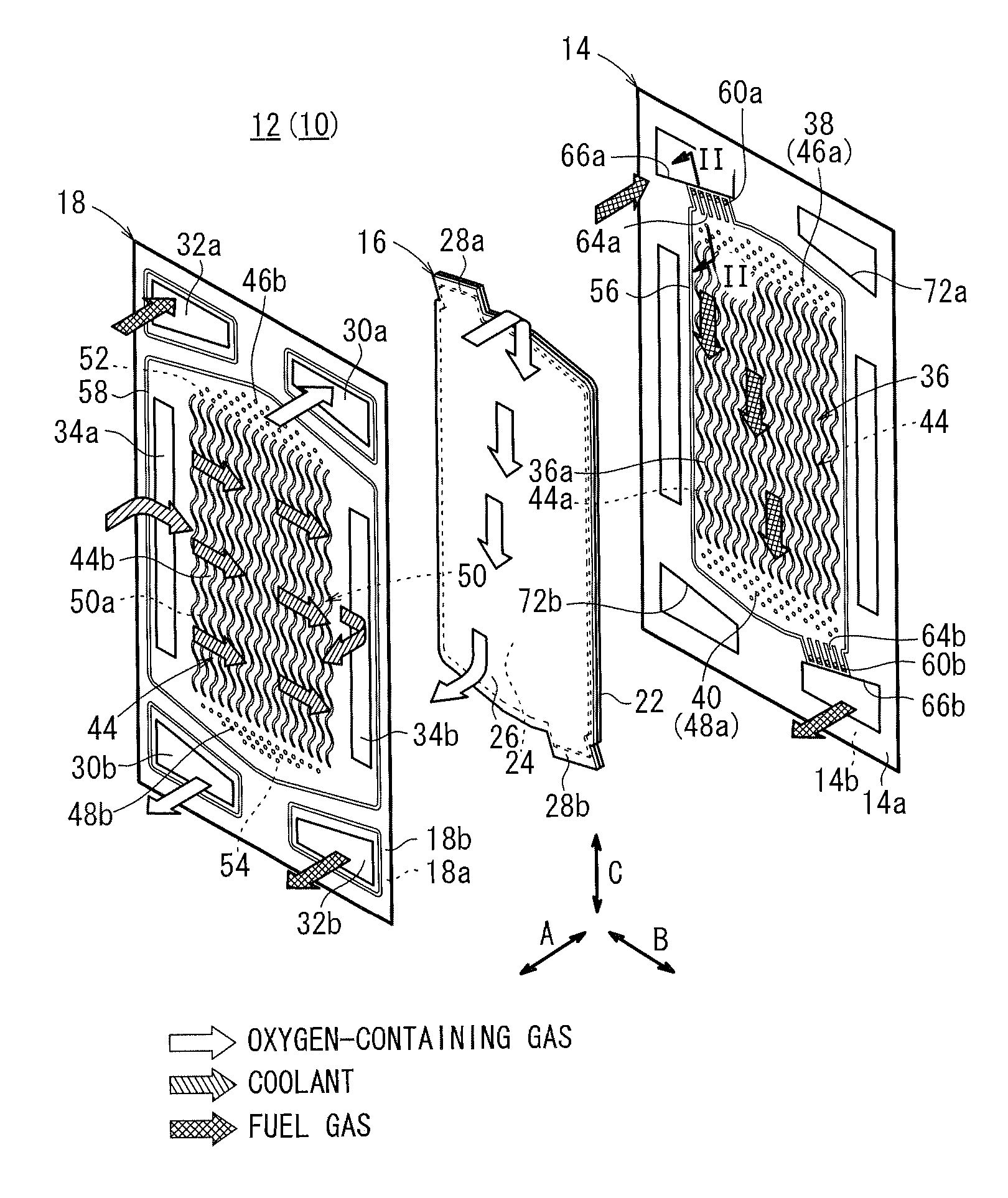
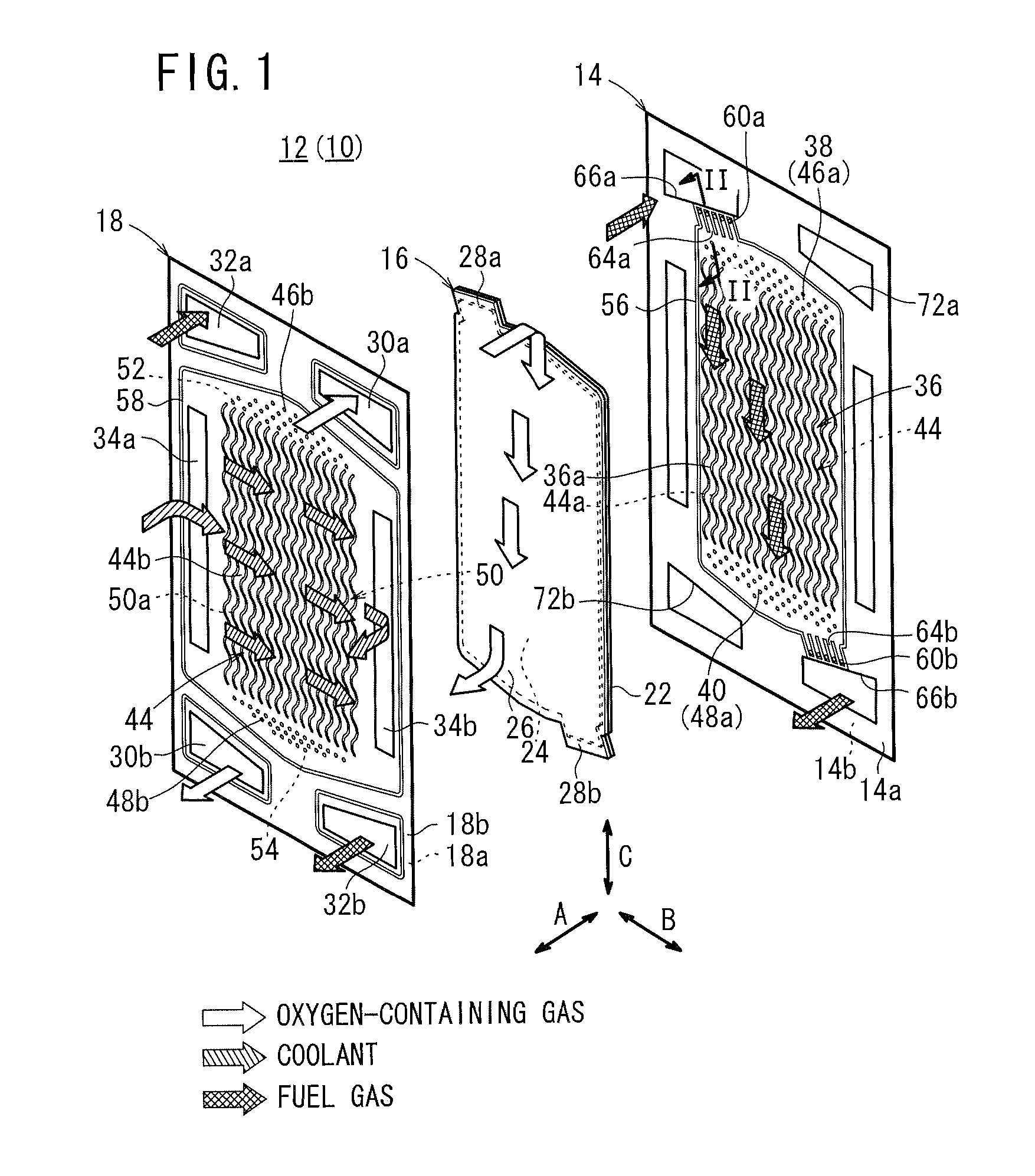
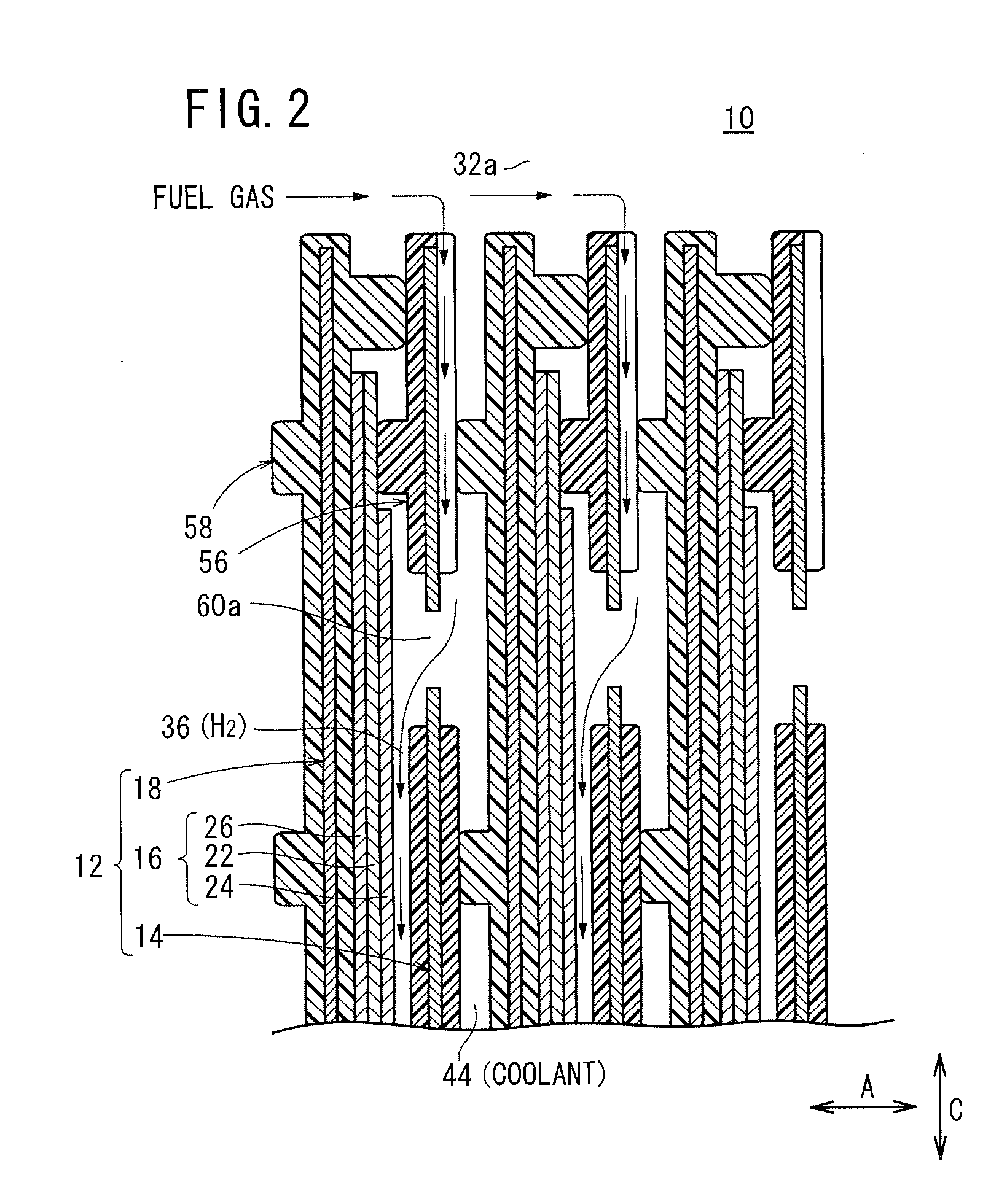
[0026]As shown in FIGS. 1 and 2, a fuel cell 10 according to the present invention is formed by stacking a plurality of power generation cells 12 in a horizontal direction indicated by an arrow A or in a vertical direction indicated by an arrow C.

[0027]Each of the power generation cells 12 includes a first separator 14, a membrane electrode assembly (electrolyte electrode assembly) 16, and a second separator 18. For example, the first separator 14 and the second separator 18 are elongated metal plates such as steel plates, stainless steel plates, aluminum plates, plated steel sheets, or metal plates having anti-corrosive surfaces formed by surface treatment.

[0028]Each of the first separator 14 and the second separator 18 has a rectangular shape in a plan view, and has a corrugated shape in cross section by corrugating a metal thin plate by press work. Instead of using the metal separators, carbon separators may be used as the first separator 14 and the second separator 18.

[0029]The ...

second embodiment

[0066]In the second embodiment, the outlet connection grooves 84 are provided in parallel with the direction perpendicular to the wall surface 72b. Therefore, the pressure loss in the oxygen-containing gas flowing through the outlet connection grooves 84 is small.

[0067]In the structure, it is possible to prevent water produced in the power generation from flowing continuously from the outlet connection grooves 84 to the oxygen-containing gas discharge passage 30b. Thus, leakage of electricity to the ground through the water produced in the power generation is prevented further reliably. Moreover, the outlet connection grooves 84 extend substantially in the direction of gravity. Therefore, the performance of discharging the water is improved easily.

third embodiment

[0068]FIG. 6 is a front view showing a second separator 92 of a fuel cell 90 according to the present invention.

[0069]The second separator 92 has a plurality of receivers 96a to 96e at a portion connecting the oxygen-containing gas supply passage 30a and the inlet buffer 52. The receivers 96a to 96e form a plurality of the inlet connection grooves 94a to 94f. The inlet connection grooves 94a to 94f are inclined from a direction (perpendicular line L3) perpendicular to a wall surface 72a of the oxygen-containing gas supply passage 30a toward the center of the oxygen-containing gas flow field 50, at different angles or at stepwise-changing angles.

[0070]Specifically, the inlet connection groove 94f provided on the center side of the oxygen-containing gas flow field 50 is inclined at a large angle from the direction perpendicular to the wall surface 72a, in comparison with the inlet connection groove 94a provided on a lateral side of the oxygen-containing gas flow field 50.

[0071]As desc...


PUM

PropertyMeasurementUnit
angleaaaaaaaaaa
areaaaaaaaaaaa
poweraaaaaaaaaa

Abstract

A fuel cell includes a plurality of power generation cells each having a first separator. The separator has a fuel gas flow field. A fuel gas supply passage extends through one corner of the power generation cell in the stacking direction, a fuel gas flowing through the fuel gas supply passage into a fuel gas flow field. An inlet buffer is provided upstream of the fuel gas flow field. The fuel gas supply passage and the inlet buffer are connected by a plurality of inlet connection grooves. The inlet connection grooves are inclined from a direction perpendicular to a wall surface of the fuel gas supply passage toward the center of the fuel gas flow field.

Description

CROSS-REFERENCE TO RELATED APPLICATION[0001]This application is based upon and claims the benefit of priority from Japanese Patent Application No. 2009-201860 filed on Sep. 1, 2009, of which the contents are incorporated herein by reference.BACKGROUND OF THE INVENTION[0002]1. Field of the Invention[0003]The present invention relates to a fuel cell including a plurality of power generation cells each formed by stacking an electrolyte electrode assembly and a separator together in a stacking direction. The electrolyte electrode assembly includes a pair of electrodes and an electrolyte interposed between the electrodes. A reactant gas flow field for supplying a fuel gas or an oxygen-containing gas as a reactant gas along one electrode is formed on one surface of the separator facing the one electrode, and a reactant gas supply passage extends through at least one corner of the power generation cell in the stacking direction for allowing the reactant gas to flow through the reactant gas...

Claims


Application Information

Patent Timeline
Patent Type & Authority Applications(United States)
IPC IPC(8): H01M8/24
CPCH01M8/0232H01M8/026Y02E60/50H01M2008/1095H01M8/242H01M8/2483H01M8/0267
Inventor KOJIMA, HIDETADAODA, MASARUSUDA, KEISUKE
Owner HONDA MOTOR CO LTD
Why Eureka
Try Eureka