Bunsen burner using lean-rich combustion type

a burner and lean technology, applied in the direction of burners, combustion types, combustion processes, etc., can solve the problems of unstable flames, increased airflow velocity of gas mixtures, back fires, etc., and achieve the effect of enhancing the stabilizing function of flames, reducing the width of burners, and easy supply

Inactive Publication Date: 2011-03-03
KYUNGDONG NAVIEN
View PDF8 Cites 11 Cited by
  • Summary
  • Abstract
  • Description
  • Claims
  • Application Information

AI Technical Summary

Benefits of technology

[0014]In a Bunsen burner according to the present invention, flame holes are formed in an inclined manner such that a flame stabilizing function is enhanced, the entire width of the burner body can be reduced, and secondary air can be easily supplied. Therefore, combustion performance is enhanced. Further, as the lean-rich combustion type is applied to the Bunsen burner, generation of pollutant materials is reduced, and flame stability is enhanced.

Problems solved by technology

However, when the combustion is performed in a low-load region, back fire may occur.
Further, when a load is increased, the airflow velocity of the gas mixture increases, forming unstable flames.

Method used


Image

  • Bunsen burner using lean-rich combustion type
  • Bunsen burner using lean-rich combustion type
  • Bunsen burner using lean-rich combustion type

Examples


Embodiment Construction

[0021]Hereinafter, example embodiments of the present invention will be described in detail with reference to the accompanying drawings.

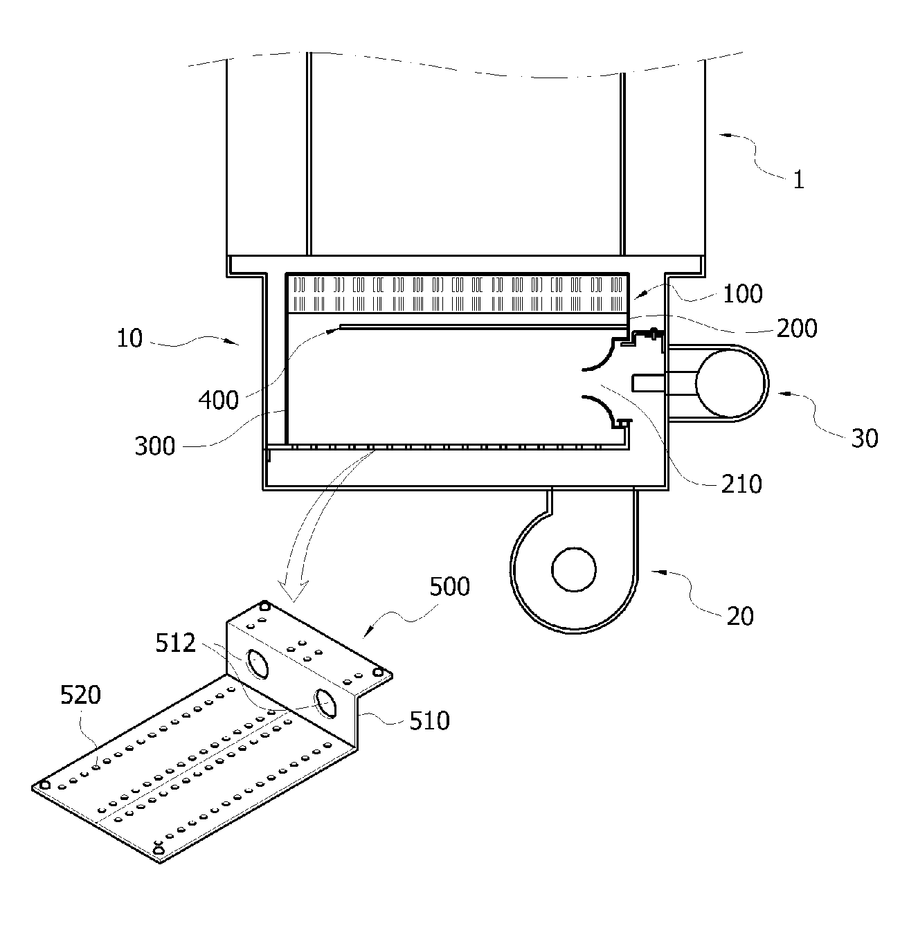
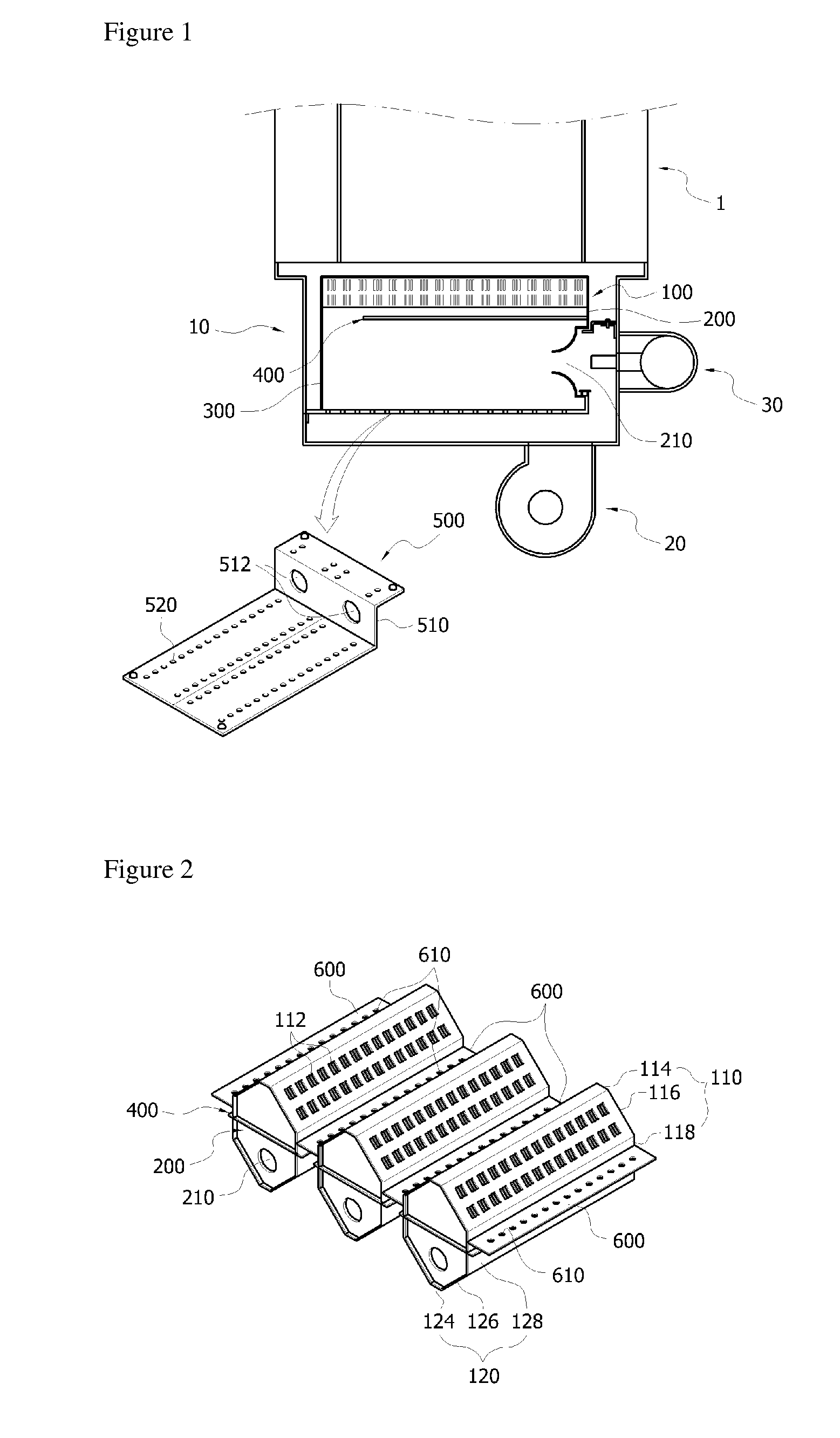
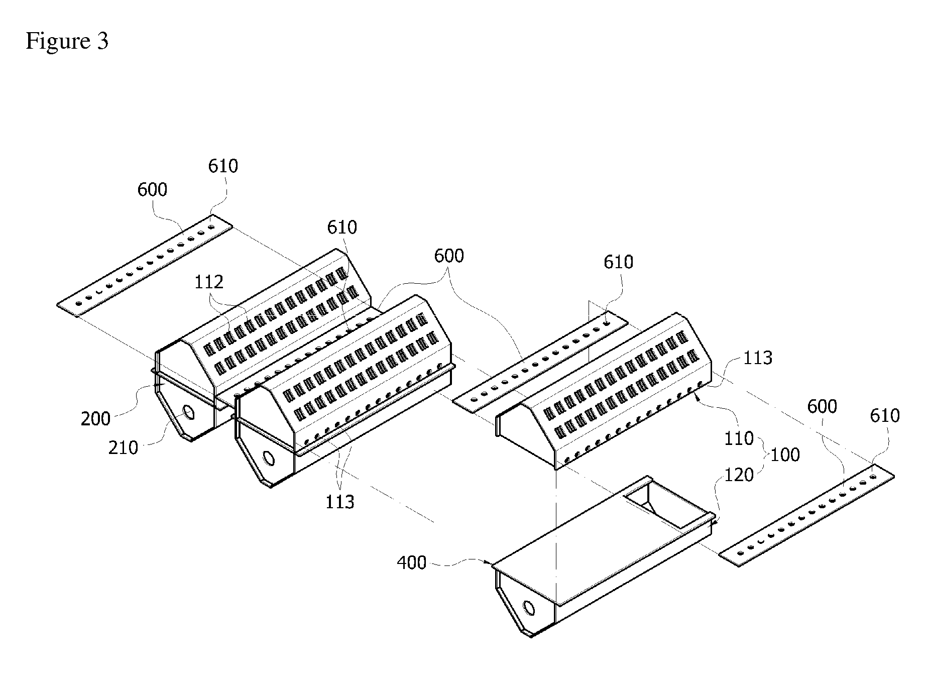
[0022]FIG. 1 is a cross-sectional side view of a burner according to the present invention. FIG. 2 is an assembled perspective view of burner bodies and connection plates according to the present invention. FIG. 3 is an exploded perspective view of the burner bodies and the connection plates shown in FIG. 2.

[0023]Referring to FIG. 1, the burner includes a casing unit 10 having an installation region formed therein, in which components of the burner are to be installed, a fan 20 which is connected and installed under the casing unit 10 so as to provide external air into the casing unit 10, a nozzle unit 30 which is connected and installed in one side of the casing unit 10 and has a leading end portion positioned inside the casing unit 10 so as to jet gas, and a burner body 100 which is installed inside the casing unit 10 so as to form flames.

[0024]A ...


PUM


Abstract

A Bunsen burner which reduces pollutant materials generated during combustion by adopting a lean combustion, enhancing combustion stability. The Bunsen burner includes burner bodies, each including: a venturi plate having a venturi hole through which a gas mixture is introduced, wherein air supplied from a fan is mixed with fuel jetted from a nozzle unit, a guide plate for guiding the gas mixture upward, an inclined portion having first flame holes for jetting the gas mixture at an oblique angle with respect to the vertical direction, a side portion that extends downward from a lower side of the inclined portion and includes through-holes through which some of the gas mixture passes, and a connection plate having opposed ends connected to the side portions of the burner bodies, respectively, and having second flame holes in which the gas mixture passing through the through-holes and secondary air, introduced by the fan and supplied along outer surfaces of the burner bodies, are mixed so that lean combustion occurs.

Description

TECHNICAL FIELD [0001]The present invention relates to a Bunsen burner using a lean-rich combustion type, and more specifically, to a Bunsen burner which can reduce pollutant materials generated during combustion by adopting a lean-rich combustion type, thereby enhancing combustion stability.BACKGROUND ART [0002]In general, combustion types for gas fuel are divided into a premixed combustion type, a diffusion combustion type, and a partial premixed combustion type. In the premixed combustion type, gas fuel and combustion air are premixed and are then supplied to a combustion chamber. In the diffusion combustion type, fuel and air are separately supplied. In the partial premixed combustion type, the premixed combustion type and the diffusion combustion type are mixed.[0003]The partial premixed combustion is performed by a Bunsen burner. The Bunsen burner premixes fuel and some of the air required for combustion as primary air, and then supplies the gas mixture. Apart from the primary...

Claims


Application Information

Patent Timeline
Patent Type & Authority Applications(United States)
IPC IPC(8): F23D14/62
CPCF23C6/045F23D14/045F23D2900/00003F23D14/64F23D2203/1026F23D14/583F23D14/04
Inventor KIM, HO-KEUN
Owner KYUNGDONG NAVIEN
Why Eureka
Try Eureka