Liquid ejection head, manufacturing method therefof, and image forming apparatus

a technology of image forming apparatus and liquid ejection head, which is applied in the direction of metal-working apparatus, printing, writing implements, etc., can solve the problems of increased die cost, increased head cost, increased image forming device cost, etc., and achieve the effect of reducing cos

Active Publication Date: 2011-03-10
RICOH KK
View PDF26 Cites 19 Cited by
  • Summary
  • Abstract
  • Description
  • Claims
  • Application Information

AI Technical Summary

Benefits of technology

[0049]The embodiments of the present invention make it possible to provide with a head of a greater length at a reduced cost.

Problems solved by technology

There is a problem that, with respect to the above-described flow channel plate and the method of manufacturing thereof, according to the above-described technique disclosed in Patent document 4, a pitch of through holes to be pressure generating chambers becomes coarse at four or five times that of a printing resolution, so that a head becomes large and an image forming device also becomes large.
Moreover, there is a problem that, as the wall sections which partition the pressure generating chamber are arranged to be formed by causing an area between the projecting sections formed on the first die to protrude, which requires large power as pressing force for press working, the wall sections need to be structured as dies which can withstand the large power, which leads to an increased cost of the dies and an increased cost of the head.

Method used


Image

  • Liquid ejection head, manufacturing method therefof, and image forming apparatus
  • Liquid ejection head, manufacturing method therefof, and image forming apparatus
  • Liquid ejection head, manufacturing method therefof, and image forming apparatus

Examples


first embodiment

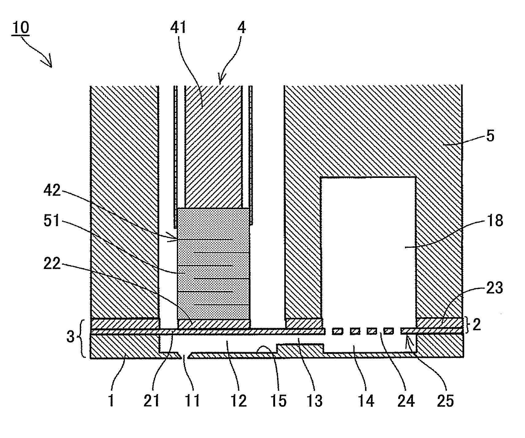
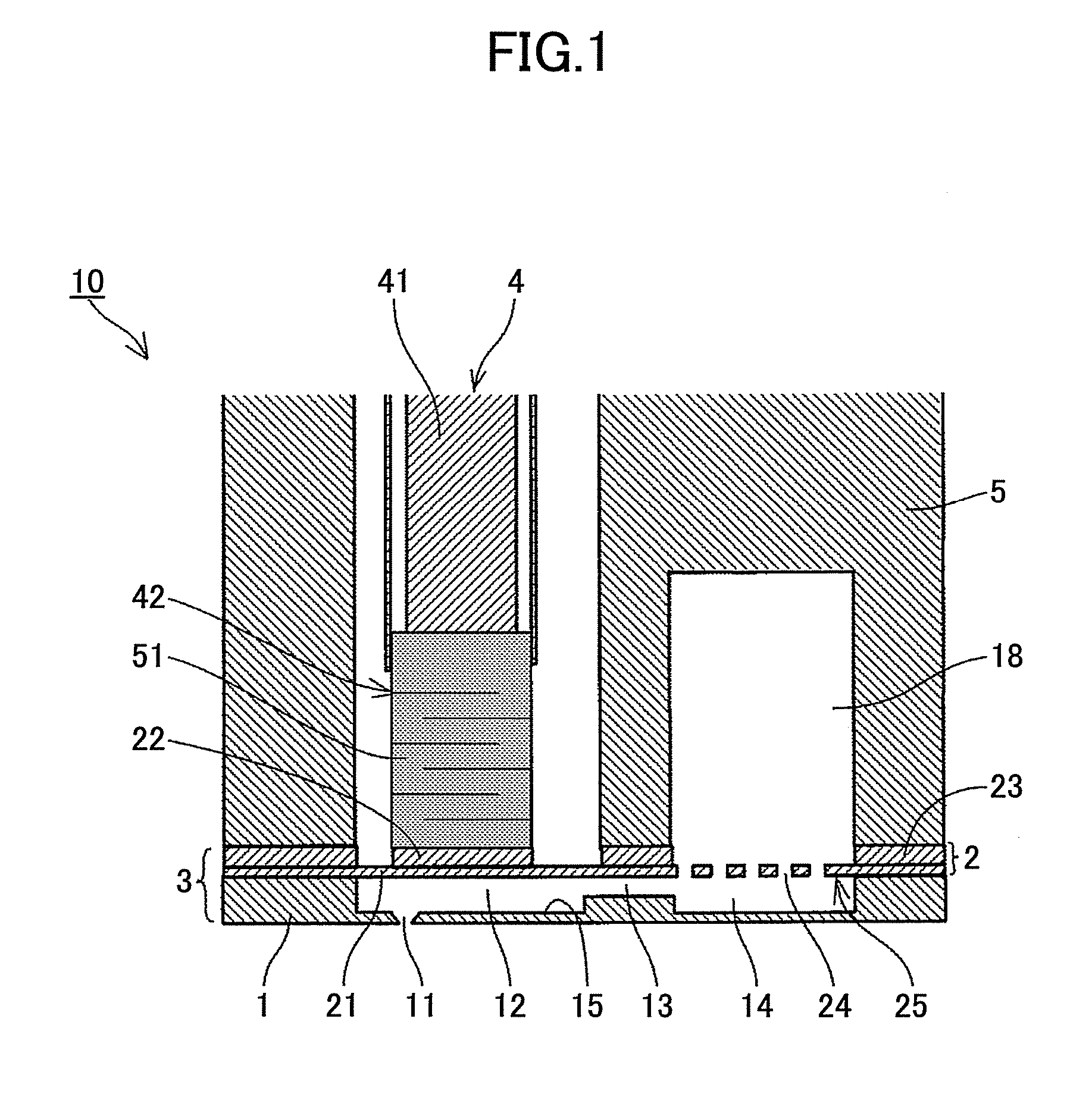
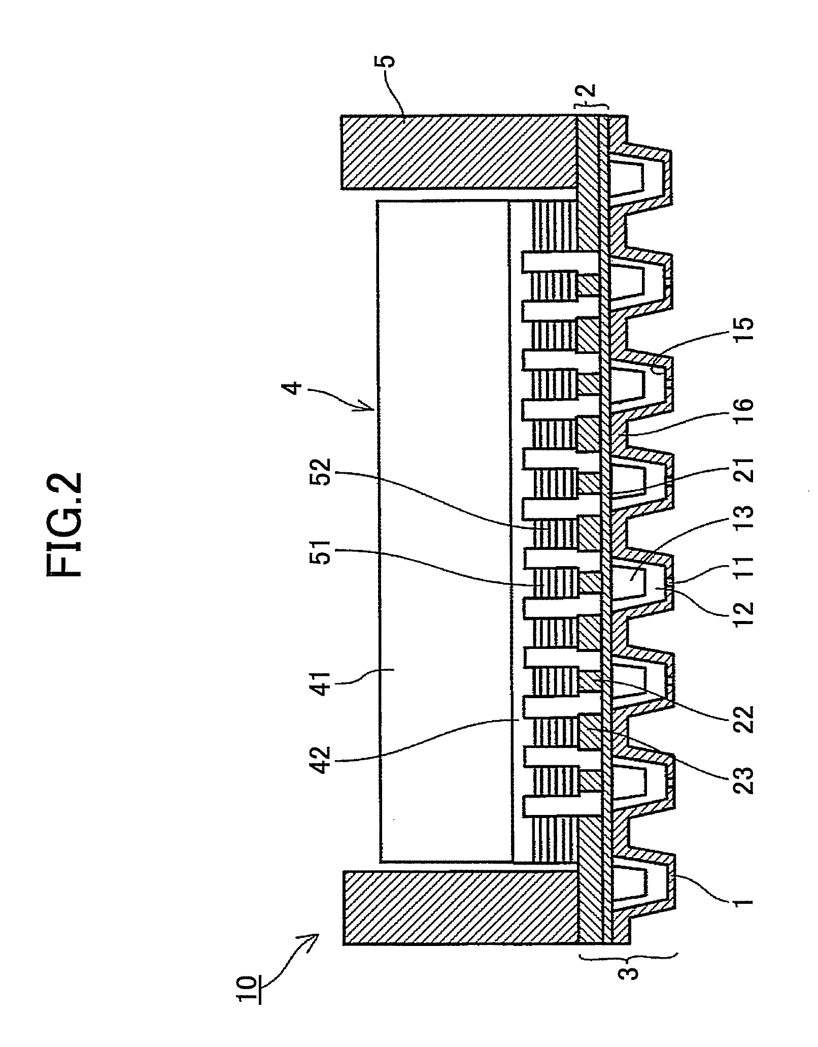
[0077]First, a liquid ejection head according to the present invention is explained with reference to FIGS. 1 and 2. FIG. 1 is a cross-sectional explanatory diagram along a direction orthogonal to a nozzle arrangement direction of the same head, while FIG. 2 is a cross-sectional explanatory diagram along the nozzle arrangement direction of the same head.

[0078]The liquid ejection head (a liquid ejection head 10) includes a flow channel unit 3 which is formed by joining a flow channel plate (a chamber plate) 1 and a vibrating plate member (a diaphragm plate) 2; a piezoelectric actuator unit 4 as an actuator unit; a frame member 5, etc.

[0079]The flow channel plate 1, which is formed of a thin plate made of a sheet of metal material, is provided with multiple nozzle holes 11 which eject liquid droplets; pressure generating chambers 12 to which corresponding nozzle holes 11 communicate; fluid resistance sections 13 which supply ink to the corresponding pressure generating chambers 12; an...

second embodiment

[0113]Next, liquid ejection head according to the present invention is described with reference to FIG. 7. FIG. 7 is a cross-sectional explanatory diagram along a nozzle arrangement direction of the same head.

[0114]The flow channel plate 1 of the liquid ejection head is formed by a half pierce work process which is one of the press working processes. In other words, after the pressure generating chamber 12 is formed, the nozzle hole 11 is formed by forging. In this case, the cross section of the pressure generating chamber 12 is substantially quadrilaterally shaped, and the face of the nozzle hole 11 may be made substantially flat. The previously-described arrangement also makes it possible to achieve the same operational advantage as the first embodiment.

[0115]Next, a fourth embodiment of the method of manufacturing the liquid ejection head according to the present invention that forms the flow channel plate of the liquid ejection head according to the second embodiment is describe...

third embodiment

[0122]Next, liquid ejection head according to the present invention is described with reference to FIGS. 11 and 12. FIG. 11 is a cross-sectional explanatory diagram along a direction orthogonal to a nozzle arrangement direction of the same head, while FIG. 12 is a cross-sectional explanatory diagram along the nozzle arrangement direction of the same head.

[0123]In the present embodiment, a flow channel plate 1 is used which has a groove-shaped indentation 115 with a shape different from the grooved-shaped indentation 15 of the flow channel plate 1 in the above-described embodiments. Explanations are omitted for the other features, which are the same as in the first embodiment.

[0124]In other words, as in the above-described embodiments, the flow channel plate 1, which is a thin plate made of a sheet of metal material, is provided with multiple nozzle holes 11 which eject liquid droplets; pressure generating chambers 12 in communication with the corresponding nozzle holes 11; a fluid r...


PUM

PropertyMeasurementUnit
sizeaaaaaaaaaa
thicknessaaaaaaaaaa
thicknessaaaaaaaaaa

Abstract

A liquid ejection head is disclosed. The liquid ejection includes a flow channel plate, the flow channel plate being formed from one thin plate, the flow channel plate being formed with one or more pressure generating chambers, a fluid resistance section which supplies liquid to the pressure generating chamber, and a nozzle hole which opposes the pressure generating chamber. The flow channel plate is made of a metal material, and wherein the flow plate includes the pressure generating chamber which is formed of a groove-shaped indentation; the nozzle hole which is formed at one end in a longitudinal direction of the groove-shaped indentation; and the fluid resistance section which is formed at the other end in the longitudinal direction of the groove-shaped indentation. The pressure generating chamber, the nozzle head, and the fluid resistance section are formed such that they deform the thin plate in a thickness direction.

Description

TECHNICAL FIELD[0001]The present invention relates to liquid ejection heads, manufacturing methods thereof, and image forming apparatuses.BACKGROUND ART[0002]As an image forming device for a printer, a facsimile, a reproducing unit, a plotter, and a multifunctional unit having these functions, an inkjet recording device is known as a liquid ejection recording-type image forming device which uses a recording head including a liquid ejection head (a liquid droplet ejection head) that ejects an ink droplet, for example. The liquid ejection recording-type image forming device ejects an ink droplet from the recording head to a sheet to be conveyed (not limited to paper and includes an OHP sheet, representing what the ink droplet and other liquid, etc., can be adhered to; also called a medium to be recorded on, or a recording medium, recording paper, a recording sheet) to perform image forming (recording, print, imaging, printing also used interchangeably). The liquid ejection recording-t...

Claims


Application Information

Patent Timeline
Patent Type & Authority Applications(United States)
IPC IPC(8): B41J2/04B21D53/76
CPCB41J2/1612B41J2/1623Y10T29/49401B41J2/1632B41J2002/14403B41J2/1625
Inventor TOBITA, SATORUKINOSHITA, MASAYUKIFUJII, KAORI
Owner RICOH KK
Why Eureka
Try Eureka