Liquid crystal display apparatus

Active Publication Date: 2011-03-10
PANASONIC LIQUID CRYSTAL DISPLAY CO LTD +1
View PDF11 Cites 9 Cited by
  • Summary
  • Abstract
  • Description
  • Claims
  • Application Information

AI Technical Summary

Benefits of technology

[0085]According to the present invention, it is possible to suppress a light leakage occurring when a pair of polarizing layers disposed so that absorption axes thereof are orthogonal to each other when observed from a normal direction is observed from

Problems solved by technology

In the IPS-mode liquid crystal display device, the deterioration in the viewing angle property resulting fr

Method used


Image

  • Liquid crystal display apparatus
  • Liquid crystal display apparatus
  • Liquid crystal display apparatus

Examples


example 1

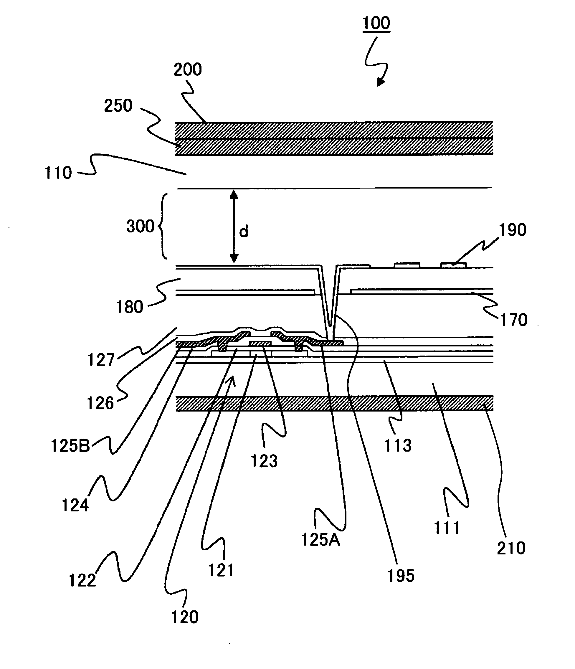
[0182]FIG. 20 is a sectional diagram showing a schematic configuration of the main parts of a pixel 1 of a liquid crystal display panel of a liquid crystal display device of Example 1. In addition, FIG. 21 is a top view showing a schematic configuration of the main parts of the pixel 1 of the liquid crystal display panel of the liquid crystal display device of Example 1. Here, FIG. 20 schematically shows a sectional structure along the line A-A′ in FIG. 21. In addition, FIG. 22 is a block diagram schematically showing an example of an overall layout of the liquid crystal display panel 100 of the liquid crystal display device of Example 1.

[0183]The liquid crystal display device of Example 1 includes the liquid crystal display panel 100 shown in FIG. 22. As shown in FIG. 22, the liquid crystal display panel 100 has a display area 2 which is provided in a region including the central portion of a second transparent substrate 111. In FIG. 22, a data driver circuit 3 that outputs image s...

example 2

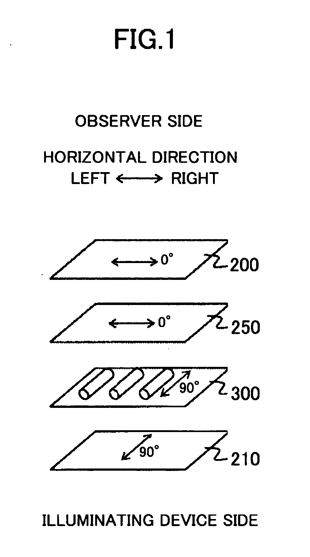
[0226]Next, another example of the present invention will be described. FIG. 25 is a sectional diagram showing a schematic configuration of the main parts of a pixel of a liquid crystal display panel that constructs a liquid crystal display device of Example 2. In addition, FIG. 26 is a top view showing a schematic configuration of the main parts of the pixel 1 of the liquid crystal display panel of Example 2. Here, FIG. 25 schematically shows a sectional structure along the line B-B′ in FIG. 26. In addition, FIG. 27 is an illustrative diagram showing an example of the relationship between the absorption axis 200A of the first polarizing layer 200, the absorption axis 210A of the second polarizing layer 210, the absorption axis 250A of the third polarizing layer 250, and the extending direction 7A of the data lines 7 when this liquid crystal display device is observed from the normal direction. In this example, the absorption axes of the first and second polarizing layers are also o...


PUM


Abstract

An E-type polarizing layer is provided between a pair of orthogonally oriented O-type polarizing layers, and alternatively, an O-type polarizing layer and an E-type polarizing layer which are oriented orthogonal to each other are provided. When a liquid crystal layer has a slow axis, the E-type polarizing layer is disposed so that an absorption axis thereof is orthogonal to the slow axis. Therefore, a liquid crystal display device having a wide viewing angle is realized in which a contrast ratio is improved by suppressing a light leakage occurring when observed from an oblique direction.

Description

CROSS-REFERENCE TO RELATED APPLICATION[0001]The present application claims priority from Japanese application JP2009-207203 filed on Sep. 8, 2009, the content of which is hereby incorporated by reference into this application.BACKGROUND OF THE INVENTION[0002]1. Field of the Invention[0003]The present invention relates to a liquid crystal display device, and more particularly, to a liquid crystal display device having at least two kinds of polarizing layers having different optical properties in order to broaden a viewing angle.[0004]2. Description of the Related Art[0005]Display devices are media that visually deliver information to people and have become very important instruments to people and societies in the modern highly advanced information world. The performance of liquid crystal display devices has been remarkably improved in recent years and used as display devices of various apparatuses such as cellular phones, personal computers, and large-screen televisions. A liquid cry...

Claims


Application Information

Patent Timeline
IPC IPC(8): G02F1/1335
CPCG02F1/133528G02F2001/134372G02F2001/133531G02F1/134363G02F1/133531G02F1/134372
Inventor ADACHI, MASAYAHIRATSUKA, TAKATO
Owner PANASONIC LIQUID CRYSTAL DISPLAY CO LTD
Why Eureka
Try Eureka