
Motion-vector computation apparatus, motion-vector computation method and motion-vector computation program

a computation apparatus and motion vector technology, applied in signal generators with optical-mechanical scanning, color televisions with bandwidth reduction, signal generators, etc., can solve problems such as poor efficiency of processing to predict motion vectors, and achieve excellent effects of providing high speed

Inactive Publication Date: 2011-03-10
SONY CORP
View PDF4 Cites 6 Cited by
  • Summary
  • Abstract
  • Description
  • Claims
  • Application Information

AI Technical Summary

Benefits of technology

[0006]In accordance with the related-art technology described above, the inter-frame prediction processing apparatus is capable of calculating an address in a memory used for storing a motion vector of a referenced object and reading out the motion vector of the referenced object from the address in the memory. It is thus possible to compute a predicted value of the motion vector at a high speed.
[0014]In addition, another effect can be obtained in the first embodiment of the present invention by providing a configuration in which the motion-vector correction section takes the frame structure as the specific structure and corrects the referenced motion vector so as to make the referenced motion vector compatible with the frame structure. That is to say, in the first embodiment of the present invention, it is possible to exhibit the other effect by providing a configuration for correcting the referenced motion vector to a motion vector compatible with the frame structure.
[0015]On top of that, a further effect can be obtained in the first embodiment of the present invention by providing a configuration in which, if the first macro block pair has the field structure, the motion-vector correction section corrects the referenced motion vector by doubling the vertical-direction component of the referenced motion vector but, if the first macro block pair is a macro block pair having the frame structure, on the other hand, the motion-vector correction section does not correct the referenced motion vector. That is to say, in the first embodiment of the present invention, it is possible to exhibit the further effect by providing a configuration for doubling the vertical-direction component of the referenced motion vector of a first macro block pair having the field structure and by not correcting the referenced motion vector of a first macro block pair having the frame structure.
[0017]That is to say, in the first embodiment of the present invention, it is possible to exhibit the still further effect by providing a configuration in which: the motion-vector predicted-value computation section employed in the motion-vector computation section computes a predicted value of a motion vector of the second macro block pair on the basis of the referenced motion vector read out from the motion-vector holding section; and if the second macro block pair has, the motion-vector predicted-value correction section employed in the motion-vector computation section corrects the predicted value of the motion vector of the second macro block pair so as to make the predicted value of the motion vector compatible with the field structure of the second macro block pair.
[0019]In addition, a still further effect can be obtained in the first embodiment of the present invention by providing the motion-vector computation apparatus with a parameter determination section configured to determine parameters, which are to be used in deblocking mode processing related to the second macro block pair, on the basis of the referenced motion vectors read out from the motion-vector holding section and on the basis of a motion vector computed for the second macro block pair and corrected so as to make the motion vector compatible with the specific structure. That is to say, in the first embodiment of the present invention, it is possible to exhibit the still further effect by providing a configuration in which the parameter determination section determines parameters, which are to be used in deblocking mode processing to be carried out as processing related to the second macro block pair, on the basis of the referenced motion vectors read out from the motion-vector holding section and on the basis of a motion vector computed by the motion-vector computation section for the second macro block pair and corrected by the motion-vector correction section so as to make the motion vector compatible with the specific structure.
[0020]In accordance with the present invention, it is possible to exhibit an excellent effect of providing a high speed at which a process is carried out to compute a motion vector in motion-vector prediction processing.

Problems solved by technology

As a result, it feared that the efficiency of the processing to predict the motion vector becomes poor.

Method used


Image

  • Motion-vector computation apparatus, motion-vector computation method and motion-vector computation program
  • Motion-vector computation apparatus, motion-vector computation method and motion-vector computation program
  • Motion-vector computation apparatus, motion-vector computation method and motion-vector computation program

Examples


first embodiment

1. First Embodiment

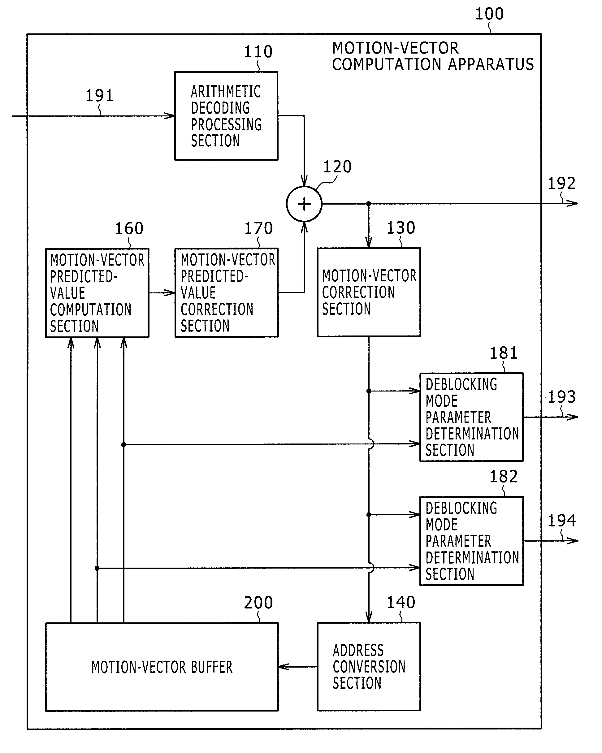
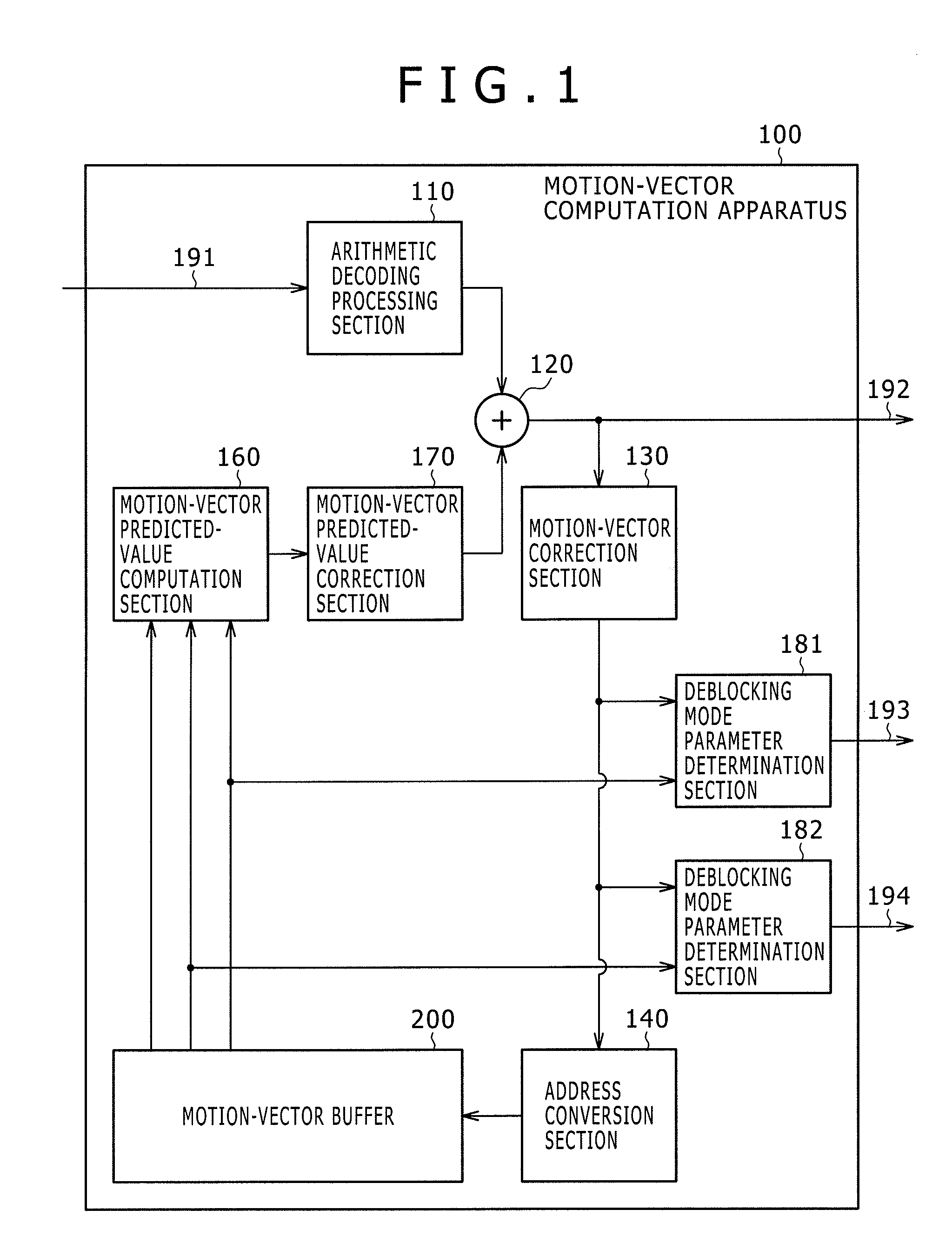
[0042]FIG. 1 is a block diagram showing a typical functional configuration of a motion-vector computation apparatus 100 according to a first embodiment of the present invention. As shown in the figure, the motion-vector computation apparatus 100 employs an arithmetic decoding processing section 110, an adder 120, a motion-vector correction section 130, an address conversion section 140 and a motion-vector buffer 200. In addition, the motion-vector computation apparatus 100 also has a motion-vector predicted-value computation section 160, a motion-vector predicted-value correction section 170, a deblocking mode parameter determination section 181 and a deblocking mode parameter determination section 182. The motion-vector computation apparatus 100 is an apparatus for computing motion vectors for a macro block pair which has either a frame structure or a field structure. The macro block pair having a frame structure is obtained as a result of a frame encoding proces...

second embodiment

2. Second Embodiment

[0157]The first embodiment of the present invention implements a typical configuration of the motion-vector computation apparatus in which the motion vector of a processing-subject macro block is computed by referencing motion vectors of macro blocks surrounding the processing-subject macro block. On the other hand, a second embodiment of the present invention implements another typical configuration of the motion-vector computation apparatus in which the motion vector of a processing-subject macro block is computed by referencing motion vectors of macro blocks of another frame referred to as a referenced frame different from the frame which includes the processing-subject macro block. That is to say, the second embodiment of the present invention implements another typical configuration in which the motion vector of a processing-subject macro block is computed in the so-called direct mode.

[0158]As described before, each of the structure of a motion vector comput...


PUM


Abstract

A motion-vector computation apparatus includes: a motion-vector correction section configured to correct a referenced motion vector to be used in a process to compute a motion vector of a second macro block pair so as to make the referenced motion vector compatible with a specific structure; a motion-vector holding section configured to store the referenced motion vector corrected to a motion vector compatible with the specific structure at an address determined in accordance with the structure of a first macro block pair; and a motion-vector computation section configured to read out the referenced motion vector from the motion-vector holding section in accordance with the structure of the second macro block pair and compute a motion vector of the second macro block pair on the basis of the referenced motion vector read out from the motion-vector holding section.

Description

BACKGROUND OF THE INVENTION[0001]1. Field of the Invention[0002]In general, the present invention relates to a motion-vector computation apparatus, a motion-vector computation method and a motion-vector computation program. More particularly, the present invention relates to a motion-vector computation apparatus for computing a motion vector for a frame by taking each of blocks composing the frame as a motion-vector computation unit, relates to a motion-vector computation method adopted by the motion-vector computation apparatus and relates to a motion-vector computation program to be executed by a computer in order to implement the motion-vector computation method.[0003]2. Description of the Related Art[0004]The MPEG (Moving Picture Expert Group) method and the H.264 method have each been known so far as a compression / coding method for compressing and coding moving-picture data. In these compression / coding methods, each of frames composing moving-picture data is divided into a plur...

Claims


Application Information

Patent Timeline
Patent Type & Authority Applications(United States)
IPC IPC(8): H04N11/02H04N19/50H04N19/105H04N19/117H04N19/139H04N19/159H04N19/176H04N19/463H04N19/513H04N19/70H04N19/85H04N19/86H04N19/91
CPCH04N19/52H04N19/43H04N19/112H04N19/61
Inventor YOSHIKAWA, HIROSHI
Owner SONY CORP
Learn More