Water barrier for footwear

a water barrier and footwear technology, applied in the field of footwear, can solve the problems of saturating the footwear affecting the comfort of wearing, etc., and achieve the effects of facilitating air exchange, reducing friction, and reducing friction

Inactive Publication Date: 2011-03-17
WOLVERINE WORLD WIDE
View PDF58 Cites 17 Cited by
  • Summary
  • Abstract
  • Description
  • Claims
  • Application Information

AI Technical Summary

Benefits of technology

[0011]In yet a further embodiment, a secondary element including a base and a mesh screen can be included in the channel between the barrier element and the exterior of the footwear. The screen can prevent dirt or debris from clogging the exit of the channel to the environment.
[0012]In still a further embodiment, the barrier element can be located adjacent the secondary element with a gap formed at least partially therebetween. The mesh screen can allow water to pass through the mesh screen to contact the barrier element. The barrier element can swell when contacted with the water that passes through the mesh screen to at least partially close the gap.
[0013]In another further embodiment, the footwear can include a sealing element joined with a barrier element. The sealing element can be located adjacent a portion of the channel, for example, a hole in the sole, that is in fluid communication with the interior of the footwear. The sealing element can be aligned with the hole

Problems solved by technology

If not addressed, such conditions can quickly saturate the footwear with water, possibly causing discomfort, blisters, and bacteria growth if not controlled.
While this technique works in some cases, it can create additional issues.
After water enters waterproof footwear, the waterproofing features typically prevent water from exit

Method used


Image

  • Water barrier for footwear
  • Water barrier for footwear
  • Water barrier for footwear

Examples


first alternative embodiment

IV. First Alternative Embodiment

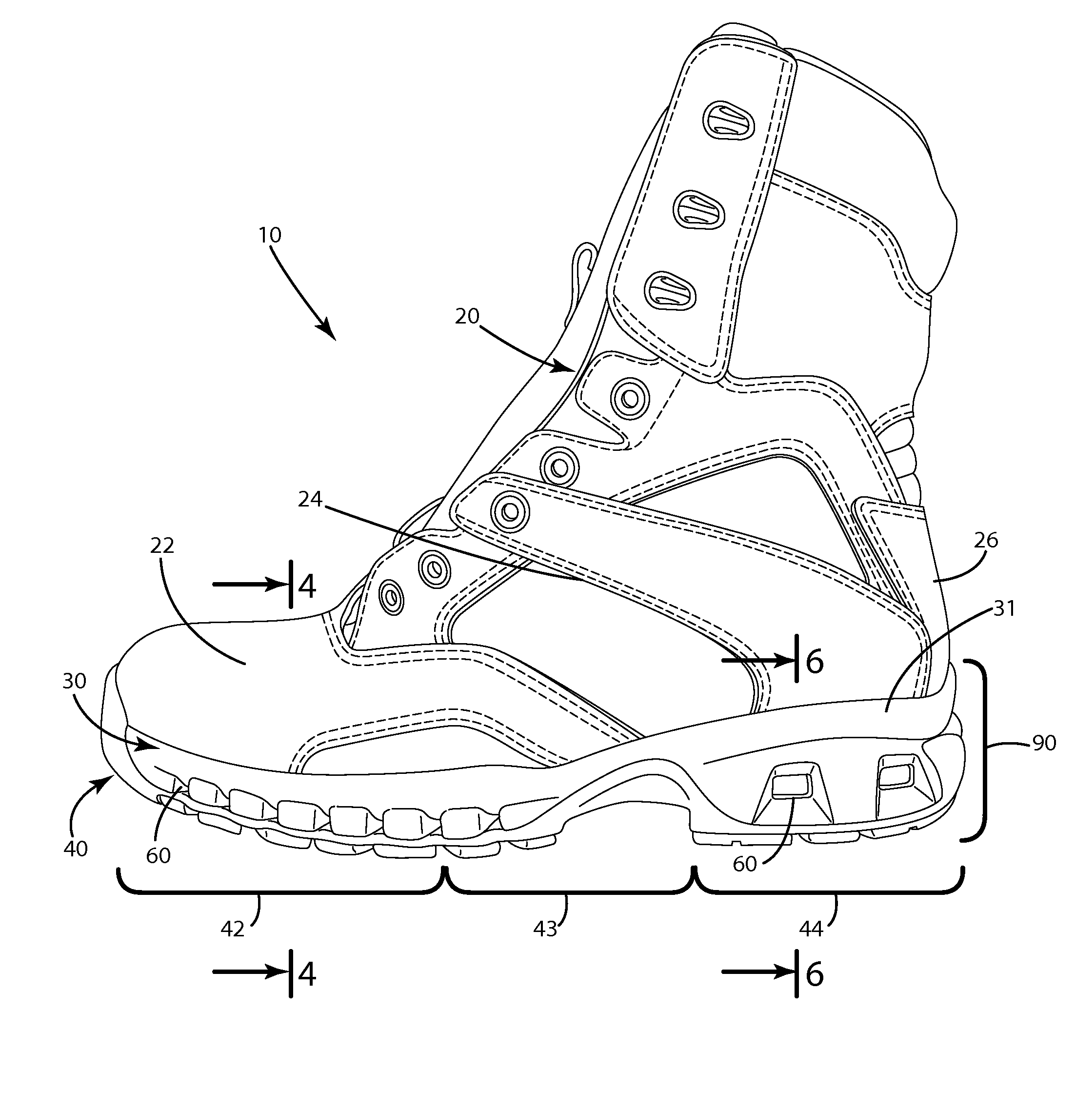
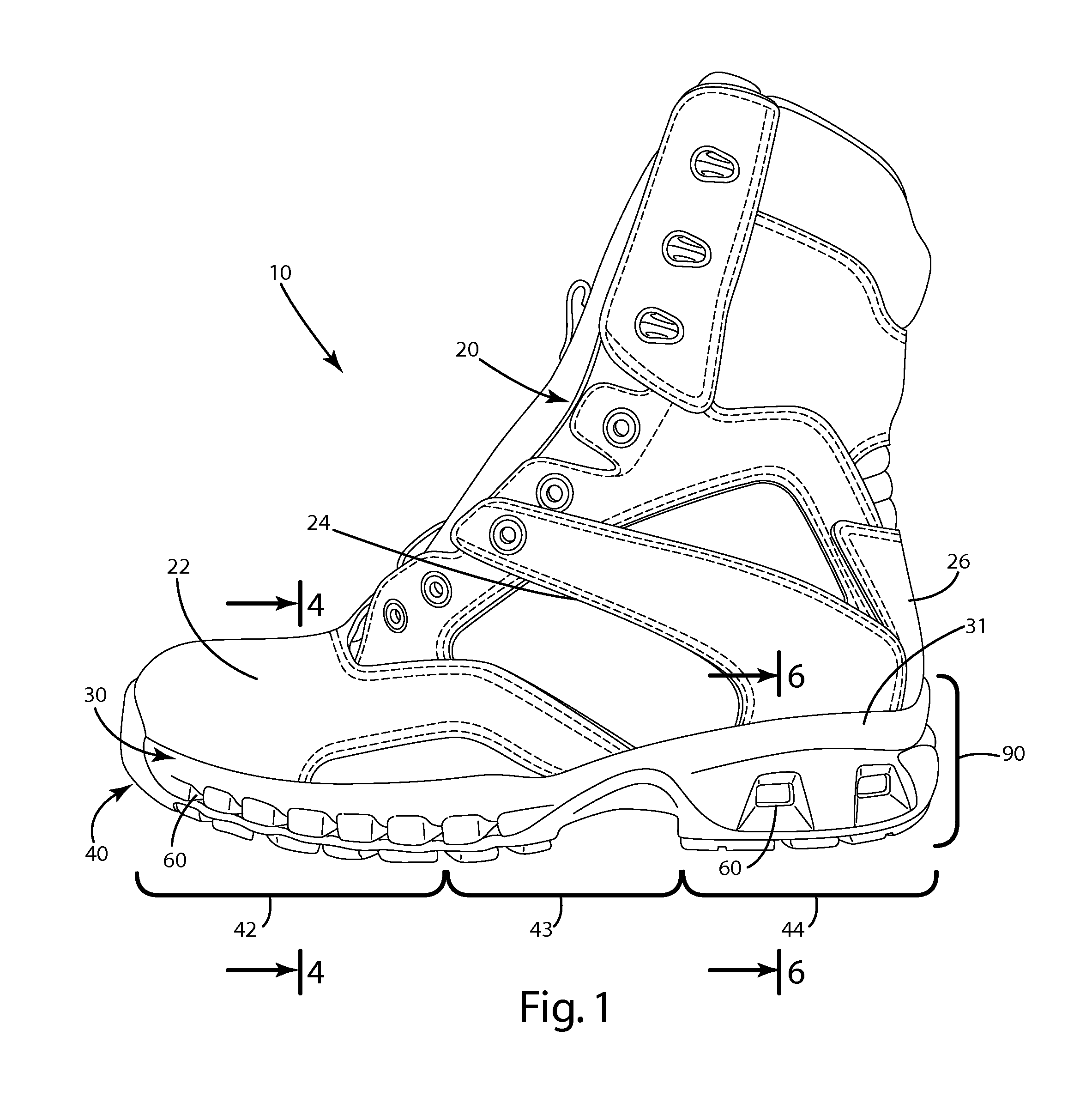
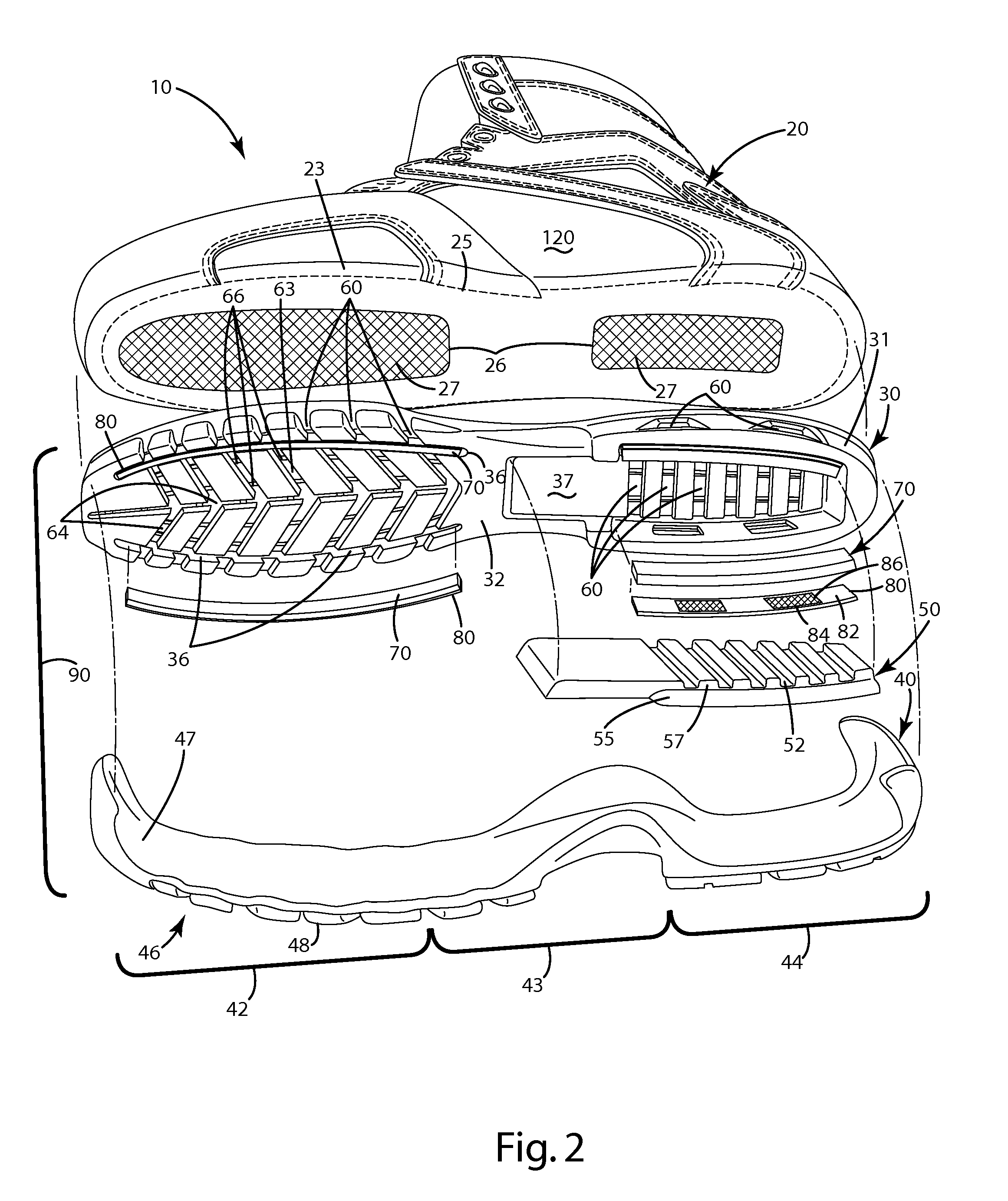
[0078]A first alternative embodiment of the footwear is illustrated in FIG. 10. This footwear is similar to the embodiment described above with several exceptions. For example, the sole 280 generally does not include a heel wedge. Instead, it includes a structure having a tray-like or u-shaped barrier element 270 positioned adjacent a secondary element 280. The secondary element 280 can include the mesh screen as described above to prevent debris from entering the footwear. The sole 280 can also define multiple sets of channels 260 and 266. The channel 260 includes an opening 261 defined in a sidewall 231 of the midsole 230. The sole 280 also can include a second larger channel 266 that extends through the outsole 240 as well as a portion of the midsole 230. The lower portion of the barrier element 270 facing the channel 266 can be adjacent a mesh 286 included in the secondary element 280. Optionally, the mesh 286 can be a completely separate element....

second alternative embodiment

V. Second Alternative Embodiment

[0080]A second alternative embodiment of the footwear 310 is generally illustrated in FIG. 11. This embodiment is similar to the embodiments described above with several exceptions. For example, instead of having channels that open through the exterior sidewalls 331 of the midsole 330, this construction can include a large channel 366 opening through the outsole 340 and the lower portion of the midsole 330 to the environment. Like the first alternative embodiment described above, a barrier element 370 can be positioned adjacent a secondary element 380. A mesh screen 386 can be positioned immediately adjacent the barrier element to prevent dirt and debris from entering the barrier element and / or the interior 120 of the footwear. The barrier element 370 can be of a generally planar configuration, in the form of a widened strip or sheet, extending across the channel 366. When dry, the barrier element allows air to travel through the channel 366 from the ...

third alternative embodiment

VI. Third Alternative Embodiment

[0081]FIG. 12 generally illustrates a third alternative embodiment of the footwear 410, which is similar to the above embodiments with several exceptions. For example, the midsole 430 and the sole 480 in general can define channels 460 extending inwardly from the sidewalls 431. These channels 431 can be in fluid communication with the interior 120 of the footwear 410. A chamber 435 can form a portion of the channels 460 as desired. The barrier element 470 can be positioned within the sidewalls 431. These barrier elements can be of a special configuration and can have a desired geometric cross section, for example, a circular, square, elliptical or other polygonal cross section, that generally matches the geometric cross section of the portion of the channels 460 within which they are positioned. A mesh screen 486 can be embedded in the material of the midsole generally between the opening 461 of the channels and the barrier element 470. The barrier el...


PUM


Abstract

A footwear construction including a barrier element that restricts the transfer of water into the footwear. The footwear can include an upper joined with a sole, with at least one of the upper and sole defining a channel that allows air to circulate to the upper. The barrier element can be located in the channel, and can include a phase change material that swells to close the channel when subjected to water. The barrier element can act as a valve to restrict the flow of water into the upper through the channel when subjected to water. The barrier element can be water absorbing polymer included in a non-woven sheet. When dry, the barrier element can allow air to pass through the channel and circulate to an interior of the upper. The barrier element can be wetted and dried repeatedly, yet still function to restrict water flow into the footwear.

Description

BACKGROUND OF THE INVENTION[0001]The present invention relates to footwear, and more particularly to footwear for outdoor use.[0002]Outdoor footwear products are typically designed to provide, among other things, comfort in a variety of environmental conditions. For example, most outdoor footwear is designed to keep feet dry when exposed to wet or damp conditions, such as that encountered when a wearer traverses water, or engages in activity in rain or snow. If not addressed, such conditions can quickly saturate the footwear with water, possibly causing discomfort, blisters, and bacteria growth if not controlled.[0003]Many manufacturers waterproof outdoor footwear to prevent water from entering the footwear and causing the above issues. While this technique works in some cases, it can create additional issues. For example, if the wearer steps in water deeper than the height of the footwear, water will fill the waterproof footwear. Water also may enter waterproof footwear by running ...

Claims


Application Information

Patent Timeline
IPC IPC(8): A43B7/06A43B7/12
CPCA43B7/08A43B17/107A43B13/125A43B7/12
Inventor NAKANO, KIYOTAKA
Owner WOLVERINE WORLD WIDE
Why Eureka
Try Eureka