
Battery counterweighted elevator

a counterweighted, battery technology, applied in the direction of elevators, mine lifts, sustainable buildings, etc., can solve the problems of increasing the power required to drive, and not being able to recover all the power expended in lifting the elevator, so as to reduce the power requirement

Inactive Publication Date: 2011-03-17
TINER JAMES L
View PDF18 Cites 26 Cited by
  • Summary
  • Abstract
  • Description
  • Claims
  • Application Information

AI Technical Summary

Benefits of technology

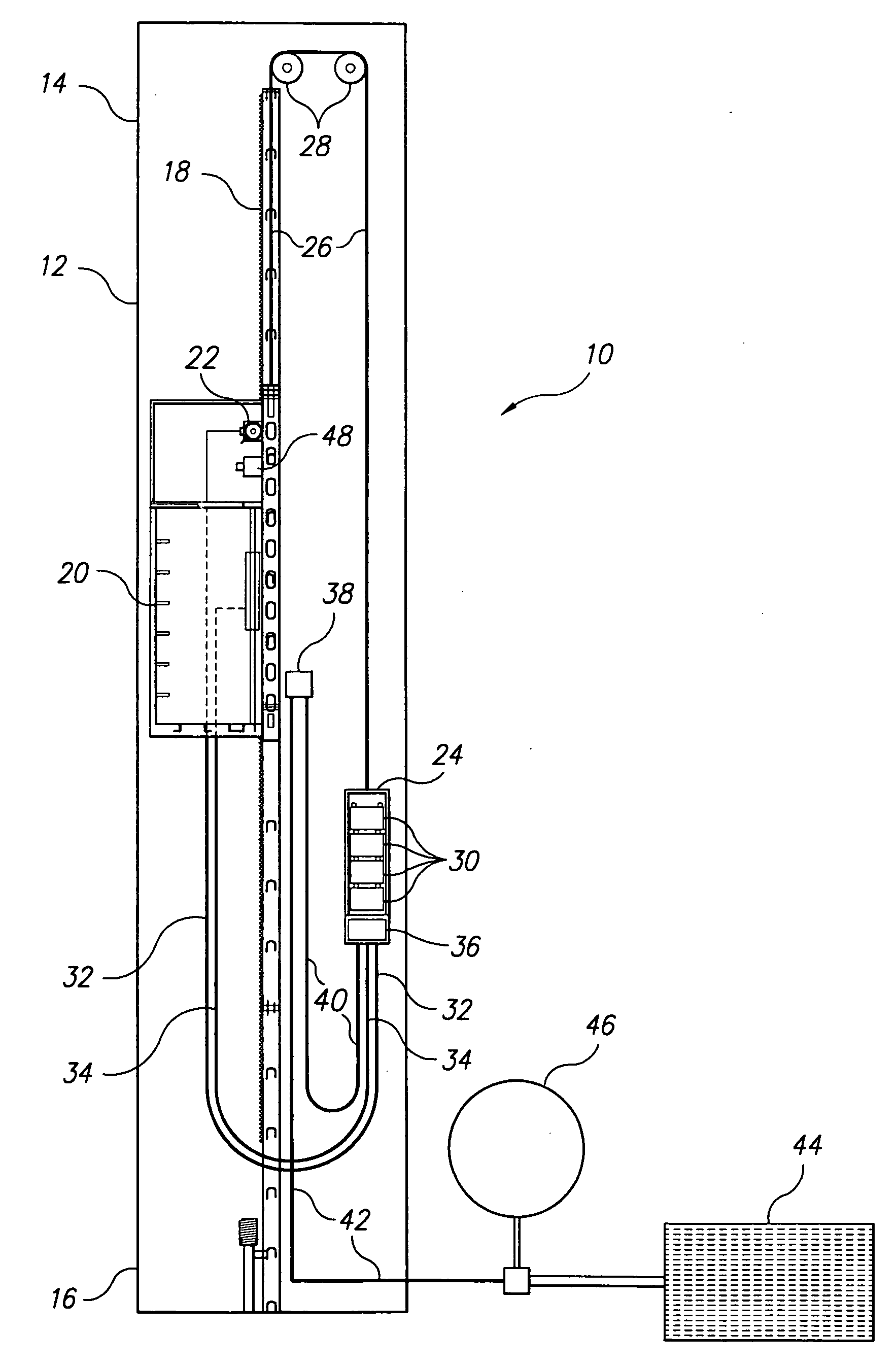
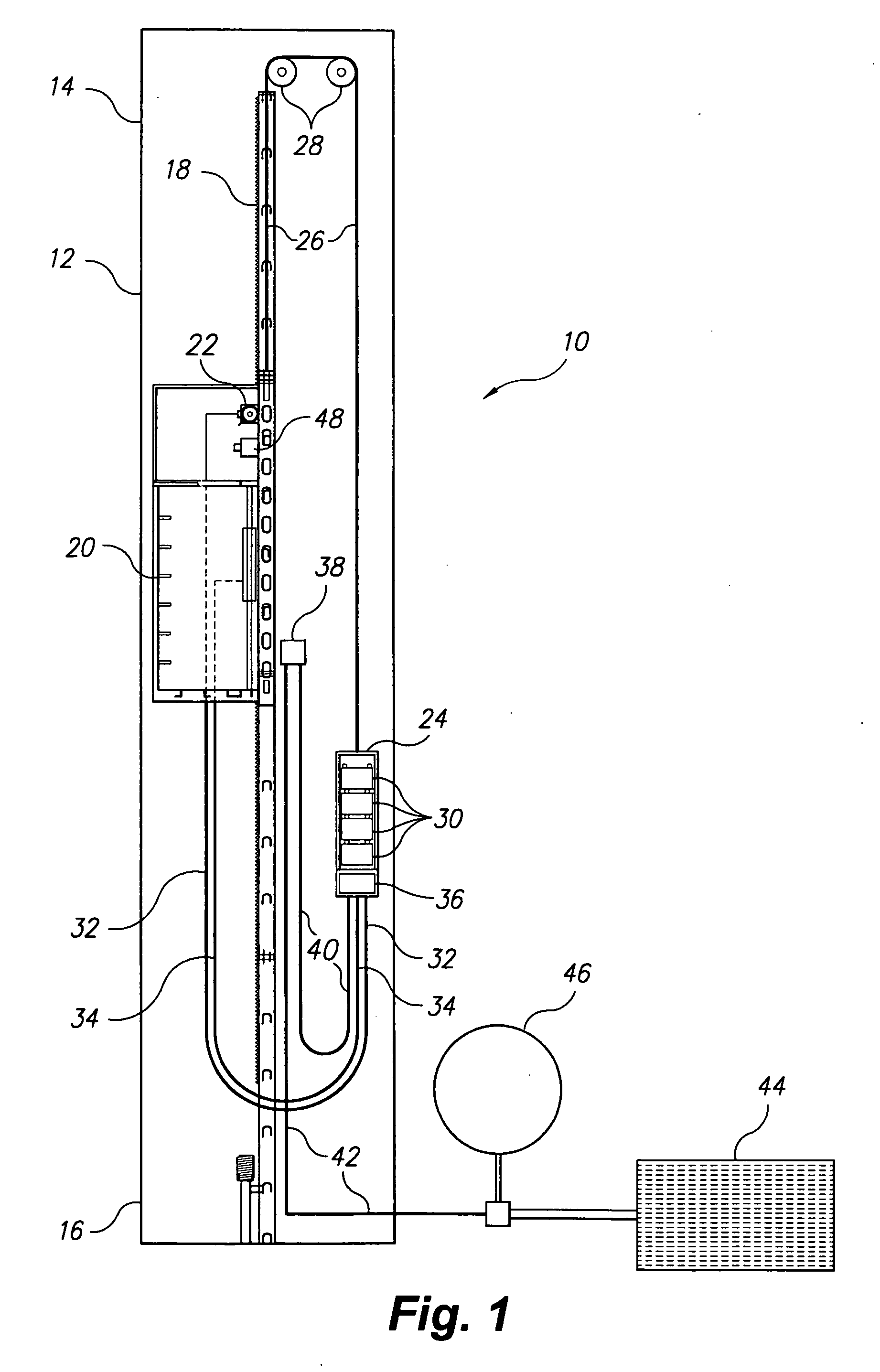
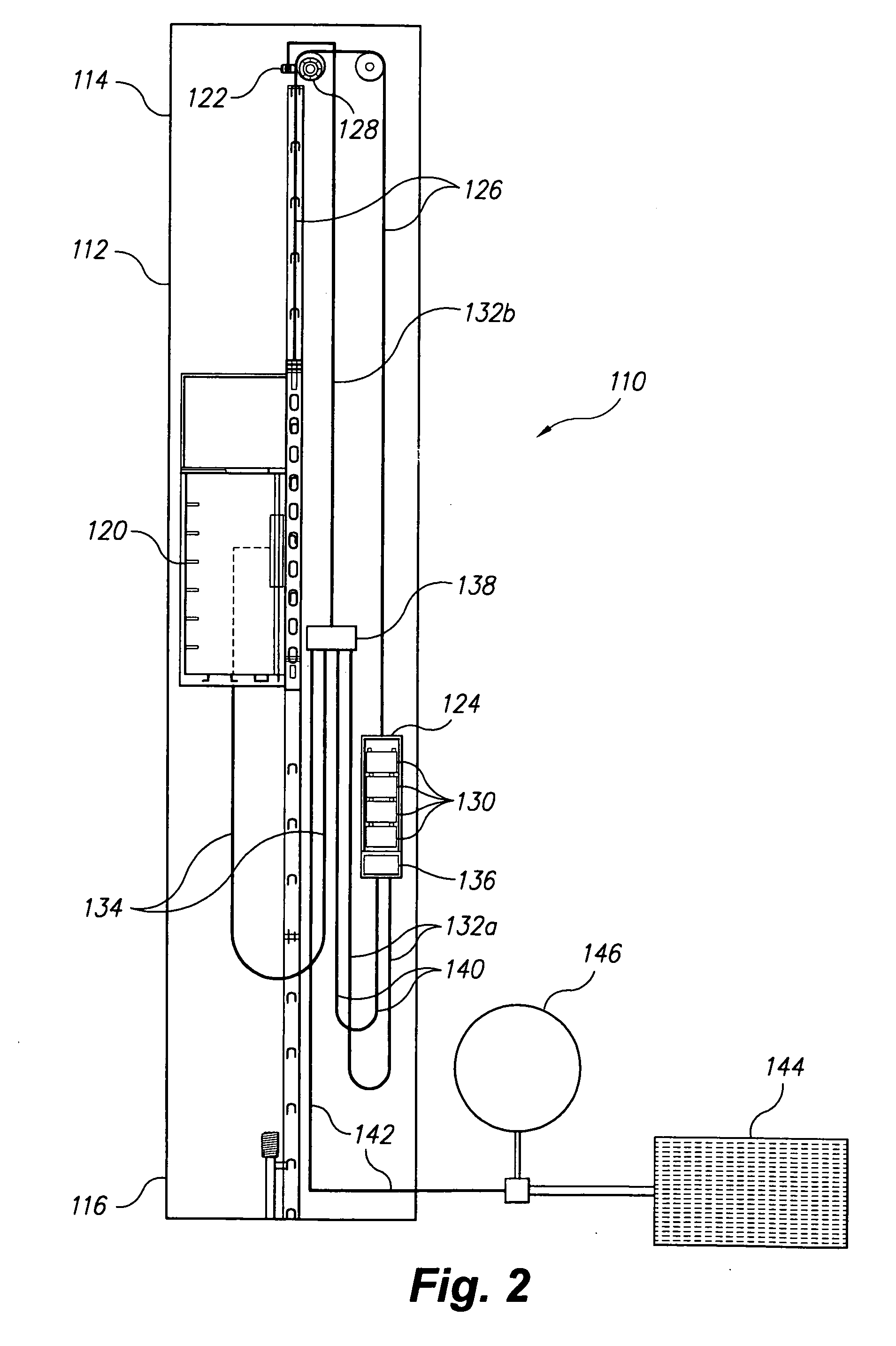
[0008]The battery counterweighted elevator may utilize either the rack and pinion or cable traction principle of operation. Either elevator type incorporates a cable-suspended counterweight assembly to reduce power requirements. Electrical power for powering the elevator is preferably provided primarily by a solar power source, although electrical power from some other external source, e.g., conventional electrical power grid, may also be provided to supplement the solar power source. Regardless of the source, the electrical power is used to charge (or recharge) a number of electrical storage batteries. The batteries also serve as the counterweight for the elevator car and its attached equipment.

Problems solved by technology

Hydraulic elevators are limited to a relatively few stories of lift height, but cable traction and particularly rack and pinion systems are relatively unlimited as to the height of the building structures in which they may be installed.
Obviously, the taller the structure, the more power is required to drive the elevator to the top.
While it is possible to recover some of that power through regenerative braking on the descent, it is not possible to recover all of the power expended in lifting the elevator.
Using the electrical power intended for other use to drive an elevator is generally regarded as inefficient, but oftentimes there is no other suitable source of elevator power available.

Method used


Image

  • Battery counterweighted elevator
  • Battery counterweighted elevator
  • Battery counterweighted elevator

Examples


Embodiment Construction

[0015]The battery counterweighted elevator comprises different embodiments of an electrically powered elevator using electric storage batteries as the power supply. The batteries are recharged from another electrical source, as needed. The batteries are installed in a counterweight used to offset at least some of the weight of the elevator car and its associated equipment. The battery counterweighted elevator system may be applied to either a rack and pinion or a cable traction elevator operating system.

[0016]FIG. 1 of the drawings provides a schematic illustration of a rack and pinion type elevator system 10 incorporating the battery counterweight. The rack and pinion elevator system 10 has a hoistway 12 with an upper end 14 and opposite lower end 16. The hoistway includes a linear toothed rack 18 extending from the upper end 14 to the lower end 16. An elevator car 20 is installed in the hoistway 12 and travels up and down the hoistway 12, as is conventional in such rack and pinion...


PUM


Abstract

The battery counterweighted elevator is adapted for rack and pinion or cable traction elevators. The elevator uses electrical power from a solar cell array to charge or recharge storage batteries, which, in turn, provide the electrical power to drive the elevator. The storage batteries serve as counterweights for at least a substantial portion of the weight of the elevator car, and travel up and down opposite the car. A traveling cable connects the elevator car with the batteries in the counterweight in the case of the rack and pinion elevator, with the cable providing power to the drive motor situated with the car and also providing control of the system from the car. The cable traction elevator has a traveling control cable extending to a fixed junction box, with power supplied from the batteries to the junction box and thence to the fixed motor at the top of the hoistway.

Description

BACKGROUND OF THE INVENTION[0001]1. Field of the Invention[0002]The present invention relates generally to elevator systems, and particularly to a battery counterweighted elevator using the rack and pinion or cable traction drive principle of operation, wherein a counterweight is provided substantially by electrical storage batteries used to power the elevator.[0003]2. Description of the Related Art[0004]Elevators generally use one of three operating principles, i.e., hydraulic, cable traction, or rack and pinion operation. Hydraulic elevators are limited to a relatively few stories of lift height, but cable traction and particularly rack and pinion systems are relatively unlimited as to the height of the building structures in which they may be installed. While most people are more familiar with elevator systems installed in taller office structures and the like, elevators, and particularly rack and pinion elevators, are often installed in tall industrial structures to facilitate m...

Claims


Application Information

Patent Timeline
Patent Type & Authority Applications(United States)
IPC IPC(8): B66B11/00B66B7/00B66B9/02B66B11/08
CPCB66B11/0461Y02B50/142B66B17/12Y02B50/00
Inventor TINER, JAMES L.
Owner TINER JAMES L
Learn More