Electronic payment card manufacturing process

Inactive Publication Date: 2011-03-17
LAU RACHEL +2
View PDF9 Cites 20 Cited by
  • Summary
  • Abstract
  • Description
  • Claims
  • Application Information

AI Technical Summary

Benefits of technology

[0009]An advantage of the present invention is that a manufacturing process is provided for a payment card that has a magnetic device in its magnetic stripe to make that portion of the recorded magnetic data reprogrammable by the internal electronics.
[0010]The

Problems solved by technology

The electronics and batteries integrated inside are up-to the challenges of years of service in the pockets and purses of their users, but the high heats and pressures briefly reached in mass producing plastics can be too much.
Such recording in

Method used


Image

  • Electronic payment card manufacturing process
  • Electronic payment card manufacturing process
  • Electronic payment card manufacturing process

Examples


Embodiment Construction

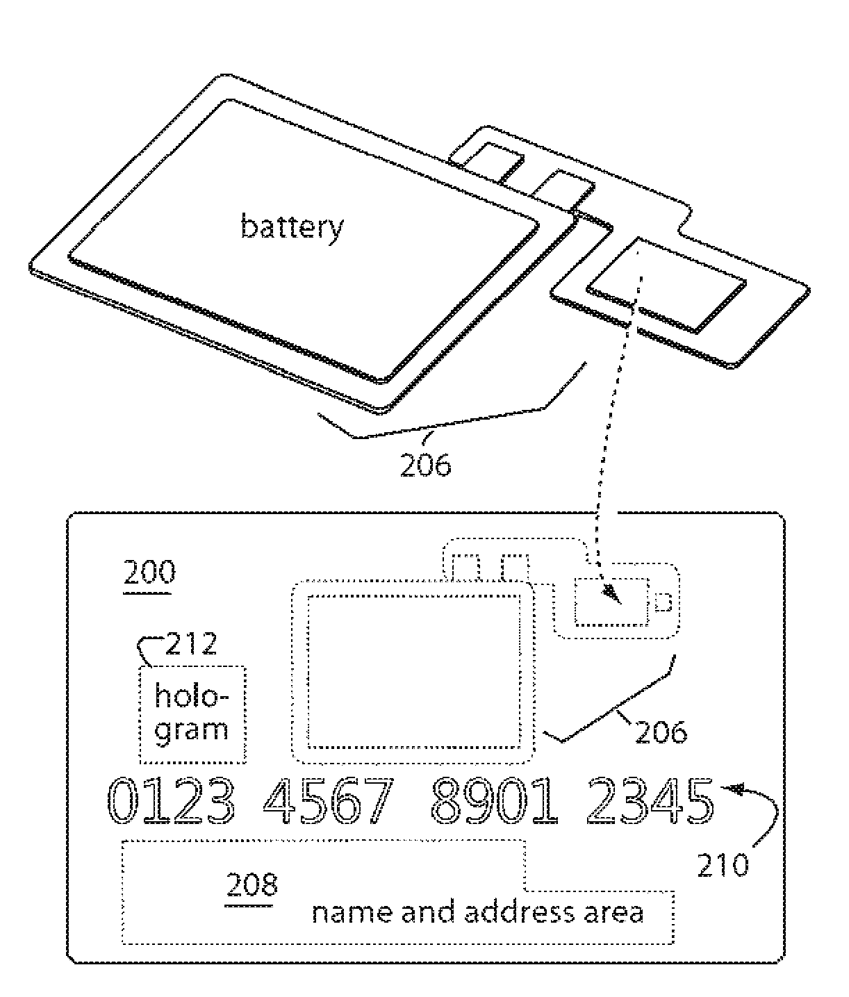
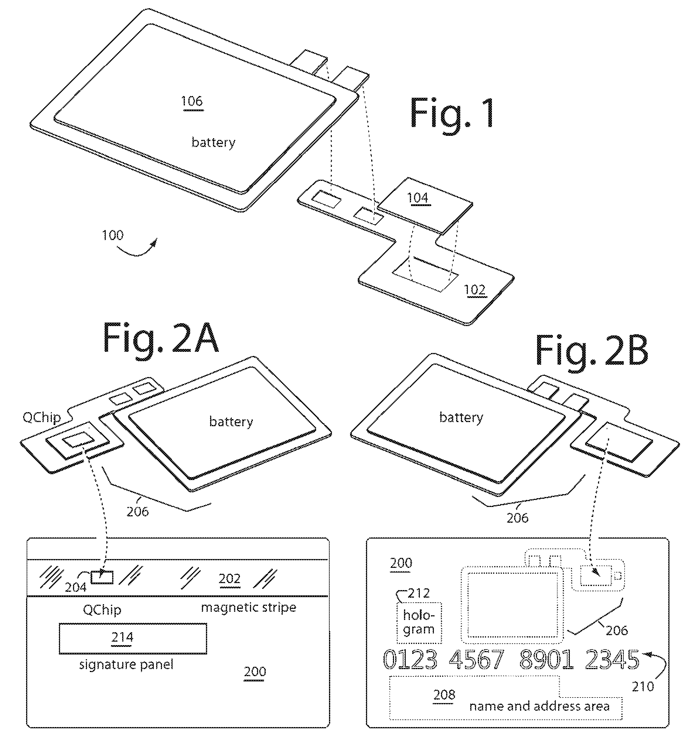
[0024]FIG. 1 represents a flexible-circuit sub-assembly (FSA) embodiment of the present invention, and is referred to herein by the general reference numeral 100. Such FSA 100 is particularly useful if installed in a magnetic-stripe type payment card. FSA 100 includes a printed flexible circuit 102 to which is mounted a an ASIC chip and QChip magnetic device 104, and a flat, flexible battery 106. The whole is thin enough to be embedded in a standard credit card, or other similar plastic payment card. A bit stripline array, on what will be the working, exposed side of the QChip magnetic device 104, is able to produce magnetic fields sufficient to write the dynamic magnetic data in such low coercivity material throughout an active area. The bit stripline is built up from many parallel sections of conductor all switched by a distributor. The current pulses through each stripline conductor section produce magnetic writing pulses to the adjacent low coercivity material. Thus new data can...


PUM


Abstract

A payment card manufacturing process for a magnetic device (QChip) with a bit coil array to individually write several dynamic magnetic data bits into the magnetic material. The magnetic device fits inside the payment card's magnetic strip and contributes to the data recorded statically in the magnetic stripe. The magnetic device edges physically nearest the leading and trailing dynamic magnetic data bits are trimmed very closely and precisely by scoring the tops with deep reactive ion etching to produce deep trenches, and then back-grinding up from underneath to the trench bottoms. The magnetic device is inserted into a high precision die or laser cut opening in the magnetic stripe in each payment card. The locations of the static magnetic bits in the magnetic stripe are precisely recorded maintaining continuous signal integrity and integration during card personalization after electronically sensing the X,Y locations of the magnetic device's dynamic magnetic data bits.

Description

BACKGROUND OF THE INVENTION[0001]1. Field of the Invention[0002]The present invention relates to magnetic data card manufacturing, and in particular to devices and methods for fabricating payments cards with magnetic stripes that can autonomously reprogram some of the magnetic data bits recorded.[0003]2. Description of Related Art[0004]Common everyday use credit cards, debit cards, and access cards, are all now including electronics and batteries to support security and anti-fraud functions. The electronics and batteries integrated inside are up-to the challenges of years of service in the pockets and purses of their users, but the high heats and pressures briefly reached in mass producing plastics can be too much.[0005]So instead of conventional high temperature, high pressure lamination processes, these electronic payment cards are made with reaction injection molded (RIM) methods that limit the temperatures and pressures suffered by the electronics embedded in the payment cards. ...

Claims


Application Information

Patent Timeline
IPC IPC(8): G06K19/06
CPCG06K19/06196G06K19/06206H01L25/18H01L2224/48091H01L2224/73265H01L2224/92247H01L2924/1461H01L2924/00014H01L2924/00
Inventor LAU, RACHELTSAO, PAULBROWN, KERRY
Owner LAU RACHEL
Why Eureka
Try Eureka