Rotation magnetic bearing with permanent magnets, preferably for a wind turbine

a magnetic bearing and permanent magnet technology, applied in the field of magnetic bearings, can solve the problem of limiting the angular flexibility of the bearing, and achieve the effect of simple and robus

Inactive Publication Date: 2011-03-17
ZEUTHEN KRISTOFFER +2
View PDF7 Cites 9 Cited by
  • Summary
  • Abstract
  • Description
  • Claims
  • Application Information

AI Technical Summary

Benefits of technology

[0006]It is therefore an objective of the invention to provide a rotational magnetic bearing that is simple and robust with the option to create other than cylindrical shapes by simple means.

Problems solved by technology

But in those examples, the basic assumption is that the bearings are cylindrical, which limits the angular flexibility of the bearings, which is a severe disadvantage in case that the shaft receives a force component in a longitudinal direction.

Method used


Image

  • Rotation magnetic bearing with permanent magnets, preferably for a wind turbine
  • Rotation magnetic bearing with permanent magnets, preferably for a wind turbine
  • Rotation magnetic bearing with permanent magnets, preferably for a wind turbine

Examples


Embodiment Construction

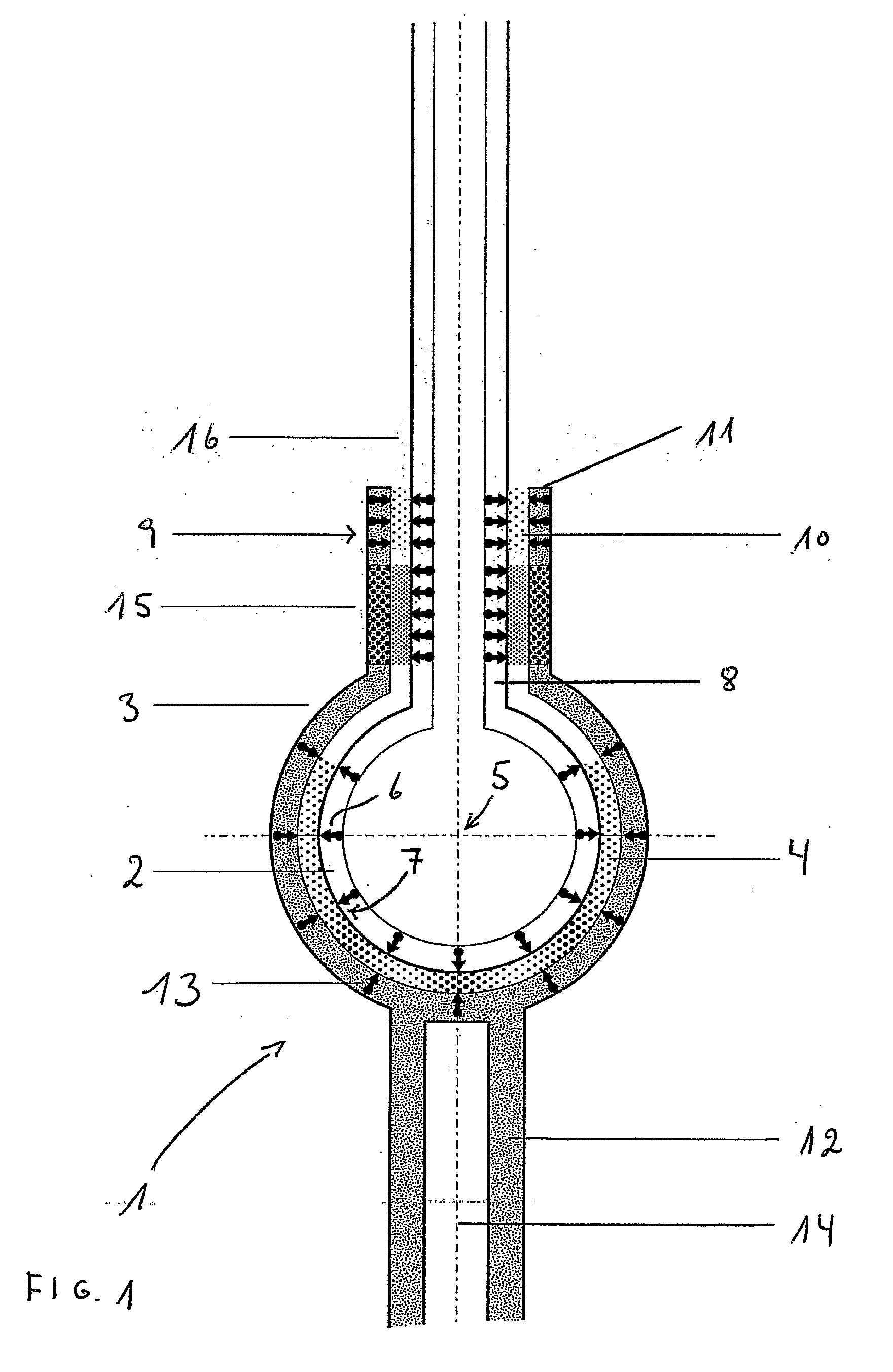
[0007]This objective is achieved by a an apparatus for rotational motion about a rotational axis of a first member relative to a second member, the first member having an outer surface being rotational symmetric about the rotational axis, and the second member having a corresponding rotational symmetric cavity with an inner surface accommodating at least part of the first member with an interspace between the outer surface of the first member and the inner surface of the second member. The first member comprises a plurality of permanent dipole magnets arranged with identical polarity directed towards the interspace and that the second member comprises a plurality of permanent dipole magnets arranged with the same polarity towards the interspace opposing the magnetic field of the first member for repulsion of the first member from the inner surface of the cavity.

[0008]Between the first and the second member, a repulsive magnetic force is provided by oppositely directed magnetic field...


PUM


Abstract

An apparatus (1) for rotational motion about a rotational axis (14) of a first member (2) relative to a second member (3), the first member having an outer surface being rotational symmetric about the rotational axis, and the second member having a corresponding rotational symmetric cavity with an inner surface accommodating at least part of the first member with an interspace between the outer surface of the first member and the inner surface of the second member. A repulsive magnetic field (4) between the first and the second member prevents contact between the outer surface of the first member and the inner surface of the second member. This magnetic field is achieved by a plurality of permanent dipole magnets (6, 13) arranged in the first member and in the second member with identical polarity (7) directed towards the interspace between the first and the second member. By using a plurality of magnetic dipoles an arbitrary shape can be provided with a surface having only north or south poles of magnets. The inventions is especially suited for rotational support of Darrieus-type wind turbines (20).

Description

FIELD OF THE INVENTION[0001]The present invention relates to magnetic bearings. Especially, the invention relates to an apparatus for rotational motion about a rotational axis of a first member relative to a second member, the first member having an outer surface being rotational symmetric about the rotational axis, and the second member having a corresponding rotational symmetric cavity with an inner surface accommodating at least part of the first member with an interspace between the outer surface of the first member and the inner surface of the second member. A repulsive magnetic field between the first and the sec- and member prevents contact between the outer surface of the first member and the inner surface of the second member.BACKGROUND OF THE INVENTION[0002]Magnetic bearings are known for a variety of application. One application is for trains, Magnetic Levitation Trains, where the train floats on a magnetic field that arises due to the permanent magnets in the bottom of t...

Claims


Application Information

Patent Timeline
Patent Type & Authority Applications(United States)
IPC IPC(8): F03D3/00H02K7/09F03D9/00
CPCF03D11/0008F05B2220/7068F16C32/0429Y02E10/725F16C2300/34H01F7/0236Y02E10/722F16C2300/14F03D80/70F16C2360/31Y02E10/74Y02E10/72F03D3/005F05B2240/212
Inventor ZEUTHEN, KRISTOFFERZEUTHEN, STEFFENBERGH, SIRI
Owner ZEUTHEN KRISTOFFER
Why Eureka
Try Eureka