Base sheet

a technology of base sheet and control circuit, which is applied in the field of base sheet, can solve the problems of difficult to obtain power sufficient to drive the control circuit of the ic chip from the interrogation signal of several hundred mw, and the manufacturing cost of the wireless ic tag/card is still relatively high, and achieves the effect of stable coupling and large allowance for the distance between the circuits

Inactive Publication Date: 2011-03-17
PHILTECH
View PDF43 Cites 140 Cited by
  • Summary
  • Abstract
  • Description
  • Claims
  • Application Information

AI Technical Summary

Problems solved by technology

However, the manufacturing cost of a wireless IC tag / card is still relatively high as an RFID; therefore, applications of a wireless IC tag / card are limited and a wireless IC tag / card has not been widely used.
However, if this method is examined precisely, it is difficult to obtain power sufficient to drive a control circuit of the IC chip from the interrogation signal of several hundred mW or so in a microwave range when attempting to ensure an actually required distance (e.g., several tens of mm) between the reader coil and on-chip coil.
This is also understood from a fact that if an estimate is made from a readable distance (approximately 40 mm) from a train ticket card (wireless IC card) using 13.56 MHz as a radio frequency, in accordance with the scaling law, the readable distance is 0.2 mm at most on a coil formed on a chip measuring 450 μm per side thereby making it extremely difficult to use the magnetic coupling method.
As described above, it is difficult for the coil provided on the ultrasmall chip to sufficiently couple with the reader / writer.
This method allows manufacturing a chip itself at low cost by using a semiconductor manufacturing process; however, the method requires mechanical work such as bending and crimping of a fine object so as to connect the chip to an antenna and requires considerably fine work.
Also, this method has a problem that there occurs a nonnegligible reduction in reliability of the connection due to stress, such as bending of the connection part with the antenna.
However, as for a method of forming a dipole antenna on a wireless IC chip, the antenna occupies most of the area of the wireless IC chip thereby making the IC chip too large.
As a result, the manufacturing cost is obviously increased to a practically unacceptable level.

Method used


Image

  • Base sheet
  • Base sheet
  • Base sheet

Examples


first embodiment

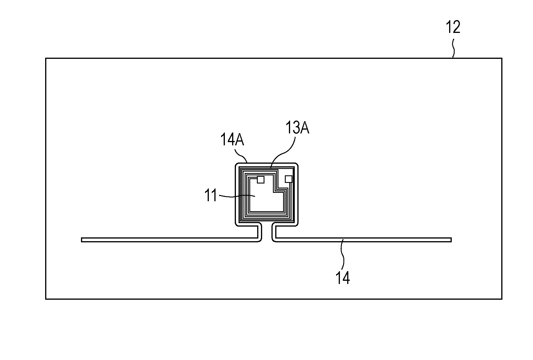
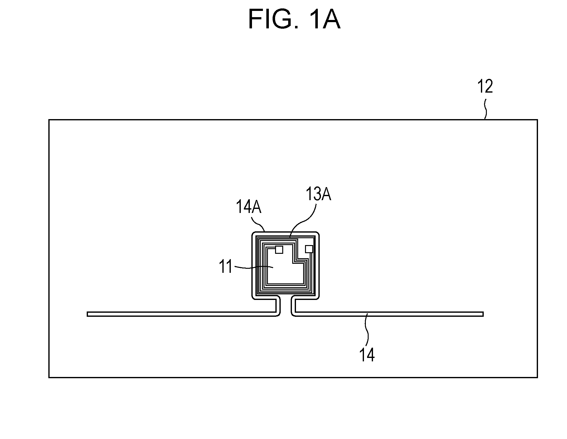
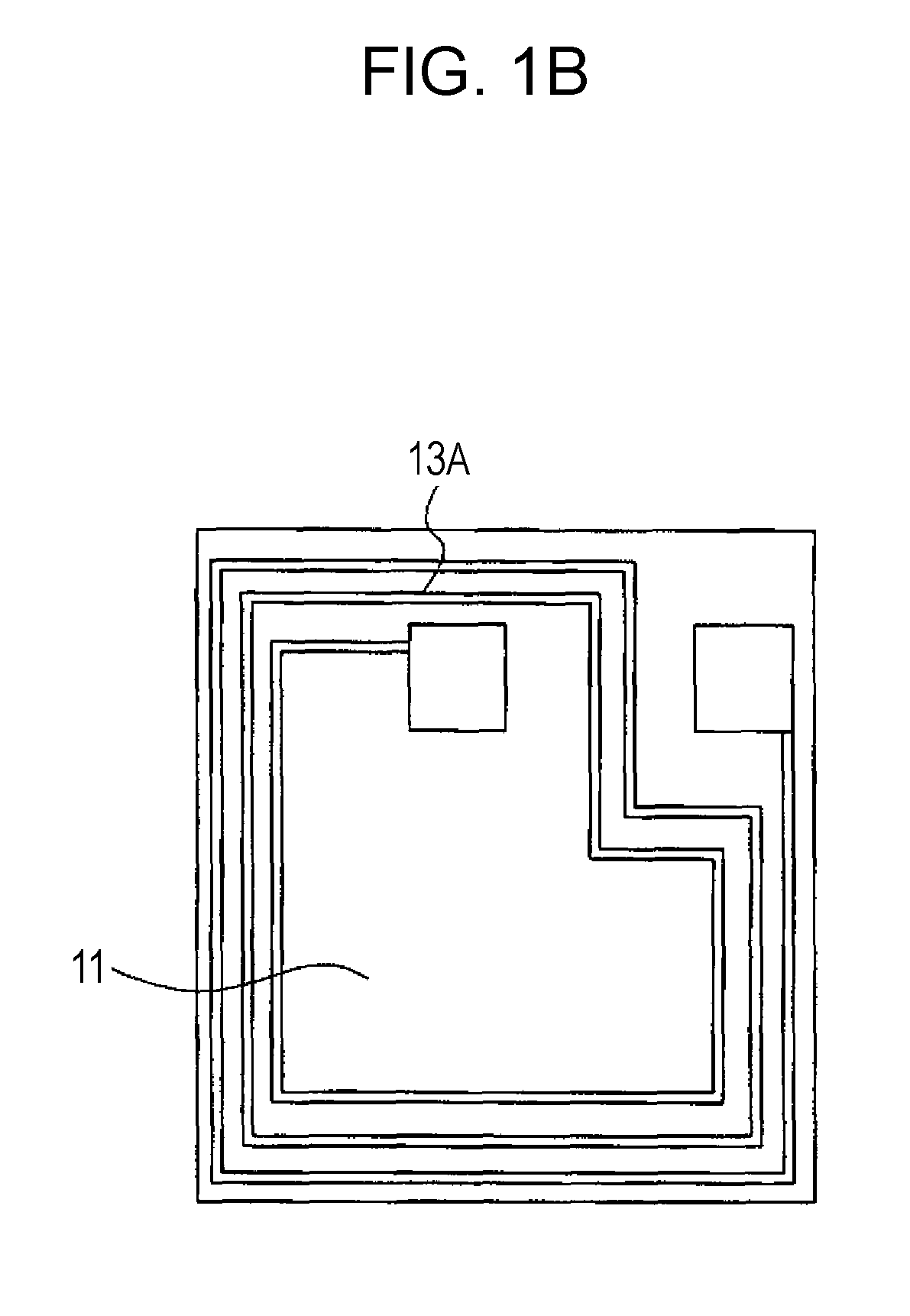
[0060]Now, referring to the drawings, an example (first embodiment) of a structure of a typical base sheet according to the present invention will be described. Plan views of this base sheet are shown in FIGS. 1A, 1B, and 2. FIG. 1A shows a plan view of the base sheet including a wireless IC chip and an antenna and FIG. 1B shows an enlarged view of only the wireless IC chip. In FIG. 1A, the wireless IC (RFID) chip is drawn on a relatively large scale in order to exaggerate the chip. “11” represents a wireless IC chip and “12” represents a base sheet. The base sheet 12 is made of a flexible sheet material such as paper. The wireless IC chip 11 is a chip formed by disposing a spiral coil 13A on an oxide film formed on a silicon substrate. The coil 13A is connected to a circuit element or a functional circuit block formed inside or on the wireless IC chip 11. An image of this connection state is shown in FIG. 1B, which is an enlarged view. Among examples of the functional circuit block...

second embodiment

[0073]Next, the present invention is shown in FIGS. 9 and 10. An antenna 92 forms a closed loop on a base sheet 91. FIG. 9 shows an example in which a wireless IC chip 93 is included in a loop-shaped coil 92A formed by the antenna 92 and FIG. 10 shows an example in which the wireless IC chip 93 is disposed outside the loop-shaped coil 92A formed by the antenna 92. In each drawing, a coil 93A of the wireless IC chip 93 and the coil 92A of the antenna 92 are magnetically coupled.

[0074]While only the coil 93A is shown on the surface of the wireless IC chip 93, the coil 93A is connected to a circuit element or a functional block, like in the wireless IC chip 11 shown in FIG. 1A.

[0075]Also in FIGS. 9 and 10, the wireless IC chip 93 is shown in an enlarged manner compared with the length of the line of the antenna 92. The actual length of the loop shape of the antenna 92 typically corresponds to the wavelength. The wireless IC chip 93 used in such a manner that it is fixed to the base she...

fourth embodiment

[0084]An example having a configuration in which multiple coupling parts are formed on one antenna and multiple wireless IC chips are disposed is shown as the present invention in FIG. 14, which is a disposition plan view. A loop-shaped antenna 142 formed on a base sheet 141 includes a meandering part (meander) 144. The meandering part 144 forms multiple coupling parts with multiple wireless IC chips 143 having different shapes. Among the wireless IC chips 143, example wireless IC chips that do not fit into the coupling part are also shown. The antenna 142 having the bent meandering part 144 as described above is called a “meander antenna.”

[0085]Among the wireless IC chips 143, example wireless IC chips straddling the meander antenna 142 are also shown. If the antenna line is disposed in such a manner that the antenna line cuts across the center of a wireless IC chip, a magnetic field having a reverse direction cuts across the wireless IC chip. As a result, magnetic coupling is not ...


PUM


Abstract

A base sheet 12 has a structure that stably couples a particular chip measuring 1 mm or less on paper with an antenna line by only disposing the chip and antenna line in such a manner that the chip and antenna line are close to each other, without electrically bringing the chip and antenna line into contact with each other. The base sheet 12 includes a chip 11 having a spiral coil 13 with at least one turn disposed on a surface of the chip, or inside the chip and near the surface thereof and an antenna line 14 having a conductor part 14A orbiting around the coil 13A of the chip 11 or directly over or directly below the coil 13A so that the conductor part is magnetically coupled with the coil 13A. This base sheet has a structure that stably couples even a chip measuring 1 mm or less on paper or the like with an antenna line by only disposing the chip and antenna line in such a manner that the chip and antenna line are close to each other, without physically bringing the chip and antenna line into contact with each other.

Description

TECHNICAL FIELD[0001]The present invention relates to a base sheet provided with a chip and an antenna. In particular, the invention relates to a technology for connecting, in a noncontact manner, to a chip including a circuit for storing information readable or identifiable on the basis of a signal wave transmitted from a reader / writer and to an antenna for receiving the signal wave transmitted from the reader / writer.BACKGROUND ART[0002]Currently, it is considered that a wireless IC tag or a wireless IC card (hereafter referred to as a “wireless IC tag / card”) is a product in the entrance to ubiquitous era. For example, an RFID (radio frequency identification / radio frequency IC tag), which is a type of a wireless IC tag / card, is used for applications such as the identification of a name plate or a product and the management of parts, materials, intermediate products, finished products, or the like in a plant, such as the assortment thereof. Wireless IC tags / cards are also used in re...

Claims


Application Information

Patent Timeline
Patent Type & Authority Applications(United States)
IPC IPC(8): H01Q1/50
CPCG06K19/07749G06K19/07756G06K19/07779G06K19/07783H01Q1/2208H04B5/0081H01Q7/00H01Q9/16H01Q21/29H04B5/00H01Q1/38
Inventor FURUMURA, YUJIMURA, NAOMINISHIHARA, SHINJIFUJINO, KATSUHIROMISHIMA, KATSUHIKOKAMIHASHI, SUSUMU
Owner PHILTECH
Why Eureka
Try Eureka