
Time shifted video communications

a video communication and time-shift technology, applied in the field of video communication systems, can solve the problems of limited appeal, lack of color imaging, and limited commercial success of picturephones

Inactive Publication Date: 2011-03-17
INTELLECTUAL VENTURES FUND 83 LLC
View PDF12 Cites 89 Cited by
  • Summary
  • Abstract
  • Description
  • Claims
  • Application Information

AI Technical Summary

Benefits of technology

[0024]The present invention has the advantage that it provides a solution for using video communications systems in a home environment where users may be engaged or disengaged with viewing the video communications system depending on what other activities are going on in the home environment.
[0025]It has the additional advantage that when remote users are not engaged in viewing the video images, the video images can be recorded for later viewing.
[0026]It has the further advantage that it provides a mechanism for both the sender and receiver of the video images to specify user preference settings to implement desired privacy rules.

Problems solved by technology

However, the Picturephone had very limited commercial success.
Technical issues, including low resolution, lack of color imaging, and poor audio-to-video synchronization affected the performance and limited the appeal.
Additionally, the Picturephone imaged a very restricted field of view, basically amounting to a portrait format image of a participant.
Thus, the images were captured with little or no background information, resulting in a loss of context.
Although such systems enabled informal communications as compared to the conference room setting, these systems were developed for work use, rather than personal use in the residential environment, and thus do not anticipate residential concerns and situations.
While reciprocity can be desirable in the work environment, it may not be desirable for communication between home environments.
It is questionable if such a display size would be suitable for the home.
This contrasts with the home setting where connecting and sharing video between multiple households may not be desired.
As such, the system was setup to provide close views of a single user and did not permit moving the system.
Researchers have largely failed to pursue translation of the media space concept from the work setting to the home setting.
While home directed media spaces have great potential to connect families over distance, assumed constraints related to privacy concerns and network bandwidth issues have limited interest in this application.
The authors recognized that personal privacy concerns are much more problematic for home users than for office-based media spaces.
Privacy encroaching circumstances can arise when home users forget that the system is on, or other individuals unwarily wander into the field of view of the system that resides in a home office.
However, while this system is located in the home, it is not intended for personal communications by the residents.
As such, it does not represent a residential communication system that can adapt to the personal activities of one or more individuals, while aiding these individuals in maintaining their privacy.
Yet this system does not provide networked support between two sites or clients, which renders the system as a standalone client and not a video communications system.
Thus, it is not possible to review recorded video from multiple connected clients using this system.
Video communication systems or media spaces within a home context do not necessarily always contain relevant or interesting video to transmit and / or record.
Furthermore, transmitting or recording unnecessary video imposes additional constraints on network bandwidth.
In particular, the challenge with many commonly available video communication systems, as well as classical media spaces, is that they are not designed to easily fit within family routines and the context of the home.
That is, they fail to address the situations and context that families need them to work within.
Taken together, these requirements make it much more difficult for families to initiate and use such technologies for everyday communication.

Method used


Image

  • Time shifted video communications
  • Time shifted video communications
  • Time shifted video communications

Examples


Embodiment Construction

[0034]The invention is inclusive of combinations of the embodiments described herein. References to “a particular embodiment” and the like refer to features that are present in at least one embodiment of the invention. Separate references to “an embodiment” or “particular embodiments” or the like do not necessarily refer to the same embodiment or embodiments however, such embodiments are not mutually exclusive, unless so indicated or as are readily apparent to one of skill in the art. The use of singular or plural in referring to the “method” or “methods” and the like is not limiting. It should be noted that, unless otherwise explicitly noted or required by context, the word “or” is used in this disclosure in a non-exclusive sense.

[0035]Families have a real need and desire to stay connected, especially when they become separated by distance. For example, they may live in different cities, or even different countries. This distance barrier can make it much more difficult to communica...


PUM


Abstract

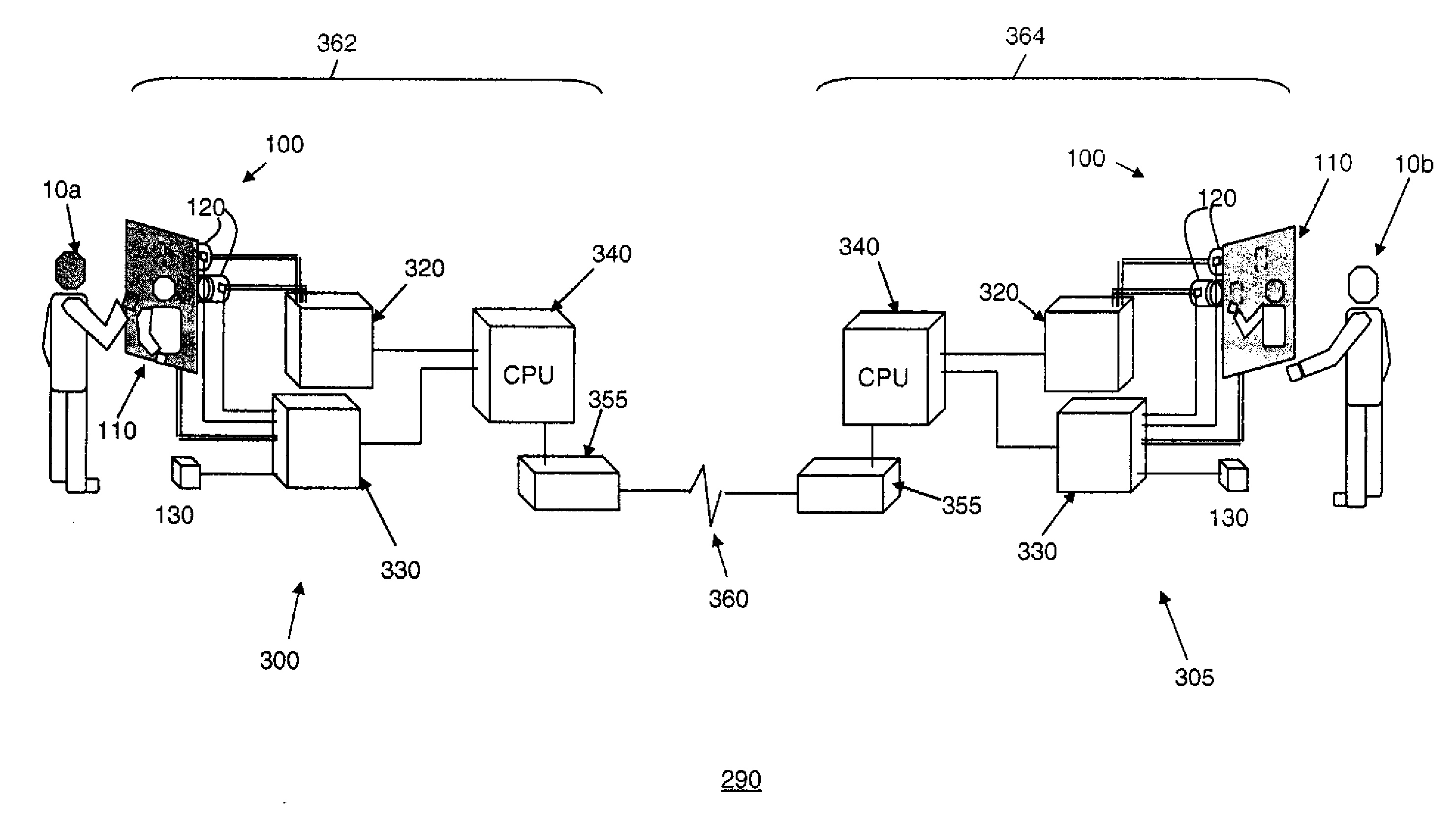
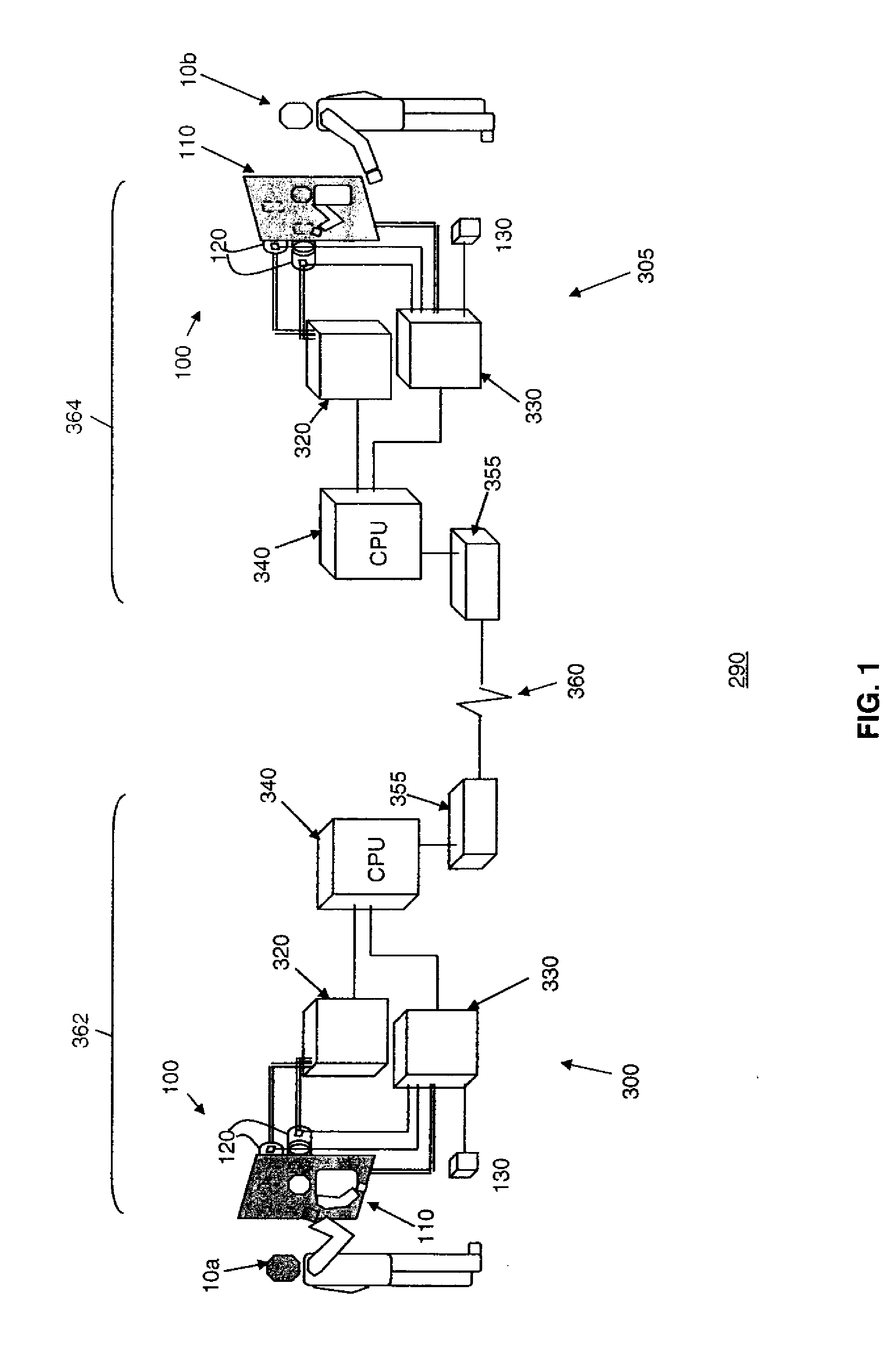
A method for providing video images to a remote viewer using a video communication system, comprising: operating a a video communication client in a local environment connected by a communications network to a remote viewing client in a remote viewing environment; capturing video images of the local environment; analyzing the captured video images with the video analysis component to detect ongoing activity within the local environment; characterizing the detected activity within the video images with respect to attributes indicative of remote viewer interest; determining whether acceptable video images are available; receiving an indication of whether the remote viewing client is engaged or disengaged; and transmitting the acceptable video images of the ongoing activity to the remote viewing client if the remote viewing client is engaged, or alternately, if the remote viewing client is disengaged, recording the acceptable video images into a memory.

Description

CROSS REFERENCE TO RELATED APPLICATIONS[0001]Reference is made to commonly-assigned co-pending U.S. patent application Ser. No. 11 / 756,532, filed May 31, 2007, entitled “A Residual Video Communication System” by Kurtz, et al., to commonly-assigned co-pending U.S. patent application Ser. No. 12 / 406,186, filed Mar. 18, 2009, entitled “Detection of Animate or Inanimate Objects” by P. Fry et al., to commonly-assigned co-pending U.S. patent application Ser. No. 12 / 408,898, filed Mar. 23, 2009, entitled “Automated Videography System” by Kurtz et al., and to commonly-assigned co-pending U.S. patent application Ser. No. 12 / 411,431, filed Mar. 20, 2009, entitled “Automated Videography Based Communications” by Kurtz, et al., the disclosures of which are incorporated herein by reference.FIELD OF THE INVENTION[0002]The present invention relates to a video communication system providing a real time video communication link between two or more locations, and more particularly to an automated meth...

Claims


Application Information

Patent Timeline
IPC IPC(8): H04N7/18
CPCH04L12/1827H04N7/147H04N7/142H04N5/144
Inventor NEUSTAEDTER, CARMAN G.JUDGE, TEJINDER K.KURTZ, ANDREW F.FEDOROVSKAYA, ELENA A.
Owner INTELLECTUAL VENTURES FUND 83 LLC
Learn More