Surface-enhanced raman scattering substrate and raman detecting system having the same

a raman scattering and substrate technology, applied in the field of surface-enhanced raman scattering substrates and raman detecting systems, can solve the problem of low utilization of carbon nanotubes

Active Publication Date: 2011-03-17
TSINGHUA UNIV +1
View PDF19 Cites 25 Cited by
  • Summary
  • Abstract
  • Description
  • Claims
  • Application Information

AI Technical Summary

Problems solved by technology

However, the wet-state dispersion of carbon nanotubes includes chemical treatments, which usually leads to some defects and low usage of carbon nanotubes.

Method used


Image

  • Surface-enhanced raman scattering substrate and raman detecting system having the same
  • Surface-enhanced raman scattering substrate and raman detecting system having the same
  • Surface-enhanced raman scattering substrate and raman detecting system having the same

Examples


Embodiment Construction

[0025]The disclosure is illustrated by way of example and not by way of limitation in the figures of the accompanying drawings in which like references indicate similar elements. It should be noted that references to “an” or “one” embodiment in this disclosure are not necessarily to the same embodiment, and such references mean at least one.

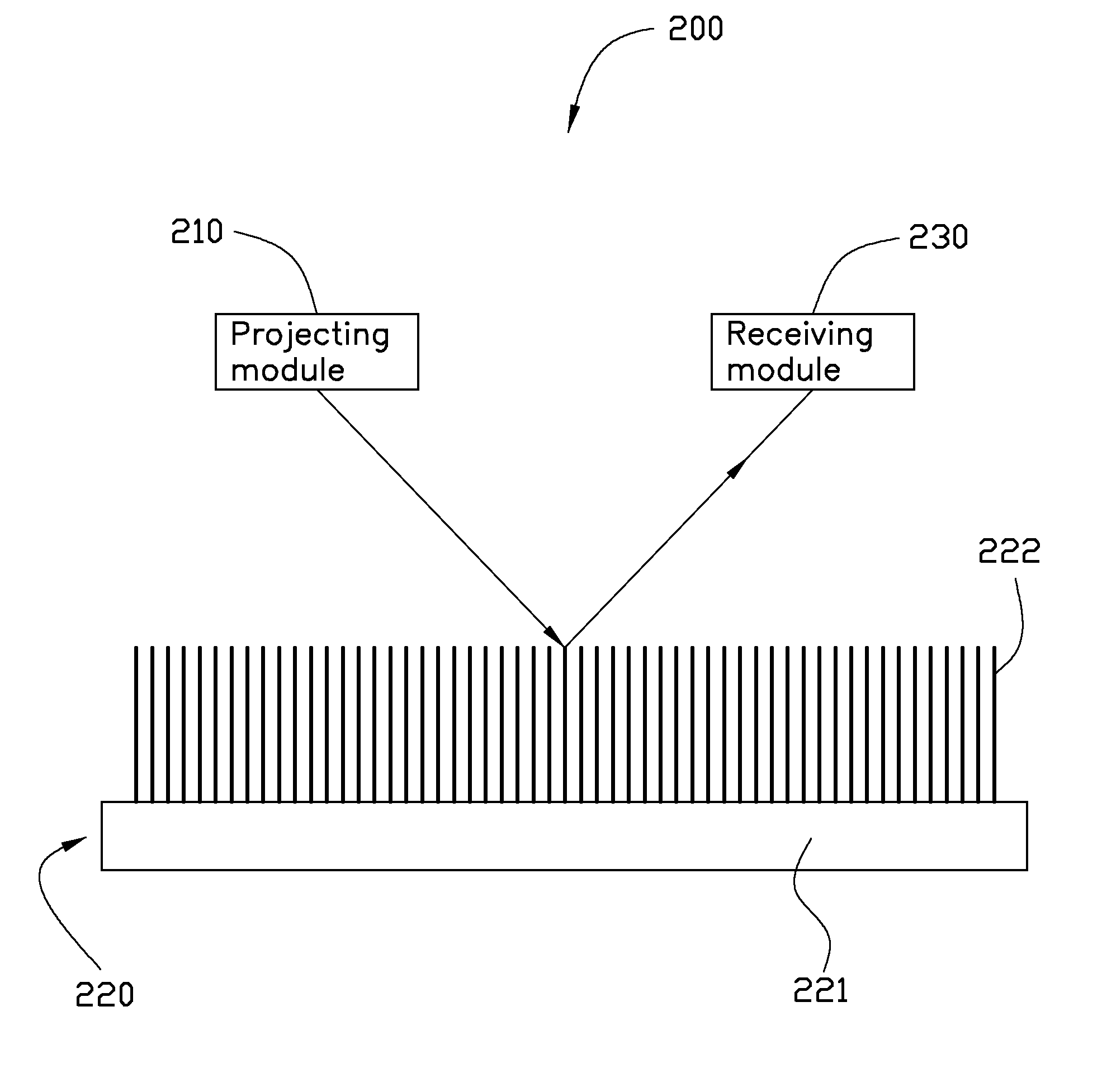
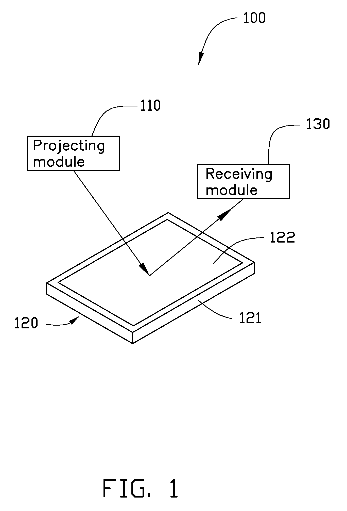
[0026]Referring to FIG. 1 of an embodiment, a Raman detecting system 100 includes a projecting module 110, a surface-enhanced Raman scattering (SERS) substrate 120, and a receiving module 130.

[0027]The projecting module 110 is configured to project a beam of light to the SERS substrate 120 to form a scattering light. Acreage of a cross section of the beam of light on the SERS substrate 120 can be less than or equal to 2 square millimeters. The projecting module 110 can include a light source such as argon laser. The light source can have a narrower frequency width. The beam of light can have a wavelength of about 450.0 nanometers to about 514.5 n...


PUM

PropertyMeasurementUnit
diameteraaaaaaaaaa
diameteraaaaaaaaaa
diameteraaaaaaaaaa

Abstract

A surface-enhanced Raman scattering substrate includes a carbon nanotube film structure and a plurality of metallic particles disposed on the carbon nanotube film structure. The carbon nanotube film structure includes a number of carbon nanotubes joined by van der Waals attractive force therebetween. The carbon nanotube film structure is a free-standing structure.

Description

CROSS-REFERENCE[0001]This application claims all benefits accruing under 35 U.S.C. §119 from China Patent Application No. 200910190213.4, filed on Sep. 15, 2009 in the China Intellectual Property Office, the disclosure of which is herein by reference. This application is related to copending applications entitled, “RAMAN DETECTING SYSTEM AND METHOD FOR USING THE SAME”, filed ______ (Atty. Docket No. US27186).BACKGROUND[0002]1. Technical Field[0003]The present disclosure generally relates to SERS (surface-enhanced Raman scattering) substrates, particularly, an SERS substrate based on carbon nanotubes, and a Raman detecting system having the same.[0004]2. Description of Related Art[0005]Fabrication of a stable SERS substrate with high enhancement has been a focus because it is a precondition for the study of SERS effect. A typical SERS substrate is usually composed of rough metal surface or coupled metal particles. In a paper entitled, “Electrochemical deposition of silver nano-partic...

Claims


Application Information

Patent Timeline
Patent Type & Authority Applications(United States)
IPC IPC(8): G01J3/44G02F1/361
CPCG01N21/65G01N21/658B82Y40/00B82Y15/00
Inventor SUN, YING-HUILIU, KAIJIANG, KAI-LIMIAO, JIAOFAN, SHOU-SHAN
Owner TSINGHUA UNIV
Why Eureka
Try Eureka