Projection lens for lighting equipment and lighting equipment using projection lens for lighting equipment

a technology of projection lens and lighting equipment, which is applied in the direction of lenses, lighting and heating equipment, instruments, etc., can solve the problems of n-sided polygon and difficult to configure the projection lens

Inactive Publication Date: 2011-03-17
STANLEY ELECTRIC CO LTD
View PDF4 Cites 25 Cited by
  • Summary
  • Abstract
  • Description
  • Claims
  • Application Information

AI Technical Summary

Benefits of technology

[0009]The projection lens for lighting equipment according to the first aspect of the disclosed subject matter is formed in the shape where N of sector-shaped lens parts each of which corresponds to the central angle 2α degrees (α=180 / N, N is an integer more than or equal to three) and is bilaterally symmetric in the rotationally asymmetric elliptical collimator lens are circumferentially disposed. According to the projection lens for lighting equipment according to the first aspect of the present invention, the projection lens for lighting equipment with the novel design which has a shape of a N-sided polygon (e.g., quadrilateral) in planar view or a shape similar to the N-sided polygon and has common edges (N edges) formed on the surface can thus be configured without impairment in function as a collimator lens.
[0011]According to the projection lens for lighting equipment of the second aspect, the shape of the rear surface of the elliptic collimator lens is formed such that the sectional shape which is to appear by section along a plane including the optical axis and the minor axis thereof and a plane parallel to the plane becomes a concave curve and a sectional shape which is to appear by section along a plane including the optical axis and the major axis thereof and a plane parallel to the plane becomes a convex curve. That is, since the shape of the rear surface of the collimator lens is formed in a rotationally asymmetric saddle-shaped surface convex along the minor axis, the capturing angle of light radiated by the light source increases in comparison with a case where the rear surface is formed as a plane or the like. In effect, the efficiency is improved in utilization of light radiated by the light source.
[0013]According to the projection lens for lighting equipment of the third aspect, since the bilaterally symmetric sector-shaped lens part is the sector-shaped lens part bilaterally symmetric with respect to the minor axis of the collimator lens, increase in oblateness of the collimator lens thus allows a configuration of the collimator lens which is more similar to the N-sided polygon in planar view. Since the sector-shaped lens part includes the saddle shaped surface convex along the minor axis as the shape of the rear surface of the collimator lens, the capturing angle of light radiated by the light source increases in comparison with a case where the rear surface is formed as a plane or the like. In effect, the efficiency is improved in utilization of light radiated by the light source.
[0018]The disclosed subject matter can provide a projection lens for lighting equipment with a novel design which has a shape of an N-sided polygon (e.g., quadrilateral) in planar view or a shape similar to the N-sided polygon and has common edges (N edges) formed on the surface without impairment in function as a collimator lens.

Problems solved by technology

However, even if the projection lens described in Patent Document 1 is improved, it may be difficult to configure the projection lens that has a shape of an N-sided polygon (e.g. quadrilateral) in planar view or a shape similar to the N-sided polygon and has common edges (N edges) formed on the surface without impairment in function as a projection lens.

Method used


Image

  • Projection lens for lighting equipment and lighting equipment using projection lens for lighting equipment
  • Projection lens for lighting equipment and lighting equipment using projection lens for lighting equipment
  • Projection lens for lighting equipment and lighting equipment using projection lens for lighting equipment

Examples


example 1

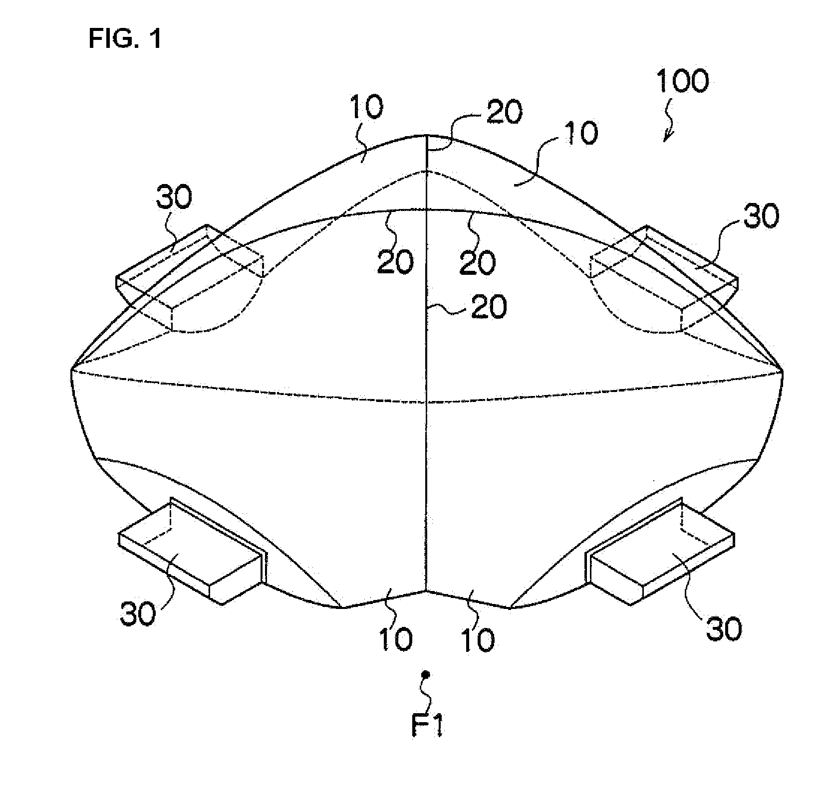
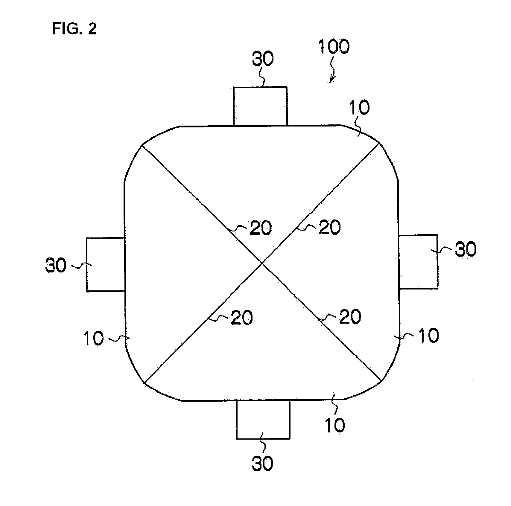
[0061]An example where the projection lens 100 of the above-described embodiment is used as a projection lens for a vehicular headlamp will be described.

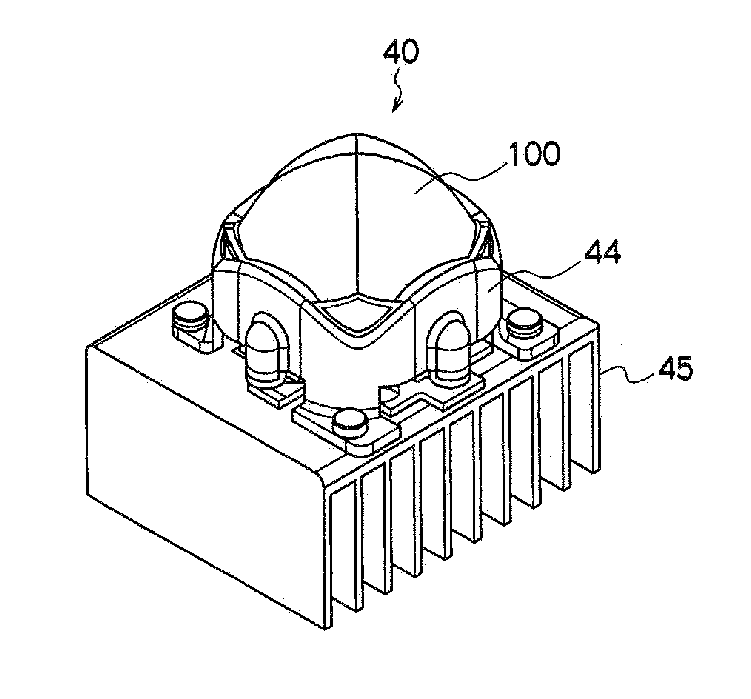
[0062]FIG. 8 is a perspective view of an exemplary direct projection type vehicular headlamp 40 that includes the projection lens 100 of FIG. 1. FIG. 9 is a sectional view of the vehicular headlamp 40 illustrated in FIG. 8 observed from a direction perpendicular to the optical axis (not illustrated).

[0063]In this example, the direct projection type lighting equipment means lighting equipment which has a light source disposed substantially at the focus F1 of the projection lens 100 and which directly projects an image of the light source in a radiating direction without intervention of a reflecting mirror.

[0064]The vehicular headlamp 40 can include an LED light source 41, a substrate 42, a shutter 43, a lens holder 44, a heat sink 45, and the projection lens 100.

[0065]The vehicular headlamp 40 can be configured such that the LED ligh...

example 2

[0071]Although the above-mentioned vehicular headlamp 40 has been described as an example of a direct projection type lighting equipment using the projection lens 100, the projection lens 100 can also be used as a following vehicular headlamp 50 as will be described below.

[0072]FIG. 10 is a sectional view of another direct projection type vehicular headlamp 50 including the projection lens 100.

[0073]The vehicular headlamp 50 is different from the above-mentioned vehicular headlamp 40 in that a light guide 51 is provided forward of the light emitting surface of the LED light source 41 with respect to the radiating direction. Accordingly, only the difference will be described in this example. Because the remaining configuration is analogous to that of the above-mentioned vehicular headlamp 40, identical reference numbers are assigned thereto and detailed description is omitted.

[0074]The light guide 51 can be made of a material having a property which allows light to pass therethrough ...

example 3

[0077]Although examples where the projection lens 100 is used in direct projection type lighting equipment has been described in examples 1 and 2 above, the collimator lens 100 can also be used for a projector type vehicular headlamp 60 having a reflecting mirror.

[0078]FIG. 11 is a sectional view of a projector type vehicular headlamp 60 including the projection lens 100.

[0079]In this example, the projector type lighting equipment means lighting equipment where a light source is disposed substantially at a first focus and an image of the light source is projected in the radiating direction via the reflecting surface and the projection lens.

[0080]The vehicular headlamp 60 can include a LED light source 61, a substrate 62, a shutter 63, a lens holder 64, a heat sink 65, a reflector 67, and the projection lens 100.

[0081]The vehicular headlamp 60 can be configured such that the LED light source 31 is disposed substantially at a first focus of the reflector 67 as described above.

[0082]Th...


PUM


Abstract

A projection lens for lighting equipment of an aspect of the present invention is characterized by formed in a shape where N of sector-shaped lens parts each of which corresponds to a central angle 2α degrees (α=180 / N, N is an integer more than or equal to 3) and is bilaterally symmetric in a rotationally asymmetric elliptical collimator lens are circumferentially disposed. The projection lens for lighting equipment of such aspect is formed in the shape where N of the sector-shaped lens parts each of which corresponds to a central angle 2α degrees (α=180 / N, N is an integer more than or equal to 3) and is bilaterally symmetric in the rotationally asymmetric elliptical collimator lens are circumferentially disposed. Accordingly, the projection lens for lighting equipment with a novel design which has a shape of a N-sided polygon (e.g. quadrilateral) in planar view or a shape similar to the N-sided polygon and has common edges (N edges) formed on a surface without impairment in function as a collimator lens can be configured.

Description

[0001]This application is a U.S. national phase filing under 35 U.S.C. §371 of PCT Application No. PCT / JP2008 / 063505, filed Jul. 28, 2008, and claims priority thereto under 35 U.S.C. §119 to Japanese patent application no. 2007-206847, filed Aug. 8, 2007, the entireties of both of which are incorporated by reference herein.TECHNICAL FIELD[0002]The disclosed subject matter relates to a projection lens for lighting equipment, and particularly, to a projection lens for lighting equipment that is applied to a projection lens and the like of a projector type headlamp mounted on a vehicle such as an automobile.BACKGROUND ART[0003]Conventionally, a projector type headlamp to be mounted on a vehicle such as an automobile has been known (e.g., see Patent Document 1). The projector type headlamp described in Patent Document 1 comprises a projection lens 300 (collimator lens) including a rotationally symmetric incident surface 310 that light from a light source (not illustrated) enters, and a ...

Claims


Application Information

Patent Timeline
Patent Type & Authority Applications(United States)
IPC IPC(8): F21V7/22G02B3/00F21V5/04
CPCF21S48/1258F21S48/1216F21S48/115F21S41/141F21S41/143F21S41/255F21S41/295
Inventor YATSUDA, YASUSHIOWADA, RYOTARO
Owner STANLEY ELECTRIC CO LTD
Why Eureka
Try Eureka