Split outer ring, split rolling bearing using the same ring and construction and method of mounting the same rolling bearing

a technology of outer ring and split outer ring, which is applied in the direction of rolling contact bearings, rotary bearings, shafts and bearings, etc., can solve the problems of radial alignment error and alignment error between the facing end portions of outer rings, and suppress the generation of noise or vibration caused by the passage of rolling elements over the mating surface. , to achieve the effect of suppressing the reduction in durability of the split outer ring and suppressing the generation of noise or vibration

Inactive Publication Date: 2011-03-17
JTEKT CORP
View PDF12 Cites 18 Cited by
  • Summary
  • Abstract
  • Description
  • Claims
  • Application Information

AI Technical Summary

Benefits of technology

[0039]According to the split outer ring and the split rolling bearing of the invention, not only can the generation of noise or vibration which is caused by the passage of the rolling elements over the mating surface be supp...

Problems solved by technology

Since the pair of split outer ring members are butted against each other at circumferential end portions thereof, there is a fear that an alignment error is caused as a result of the split outer ring members moving in an axial direction relatively to each other.
In addition, in the split rolling bearing, while the circumferential end faces of the set of two split outer ri...

Method used


Image

  • Split outer ring, split rolling bearing using the same ring and construction and method of mounting the same rolling bearing
  • Split outer ring, split rolling bearing using the same ring and construction and method of mounting the same rolling bearing
  • Split outer ring, split rolling bearing using the same ring and construction and method of mounting the same rolling bearing

Examples


first embodiment

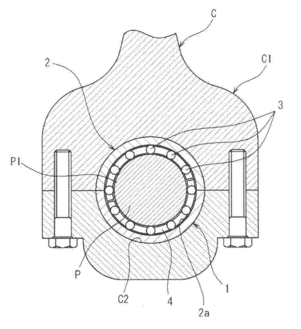
[0057]Next, preferred embodiments of the invention will be described by reference to the accompanying drawings. FIG. 1 is a side view showing the construction of a split rolling bearing according to a first embodiment of the invention. This split rolling bearing 1 is interposed, for example, between an outer circumference of a crankpin P and an inner circumference of a large end portion C1 of a connecting rod C of an internal combustion engine and supports the connecting rod C so as to oscillates freely relative to the crankpin P.

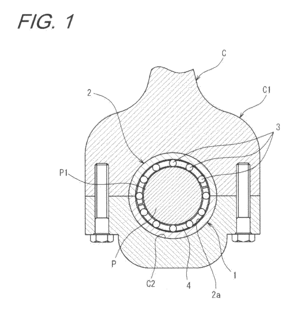
[0058]This split rolling bearing 1 has a split outer ring 2 which inscribed in an inner circumferential surface C2 of the large end portion C1, a plurality of cylindrical rollers 3 which are disposed rollingly between a raceway surface 2a which is formed on an inner circumferential side of the split outer ring 2 and an outer circumferential surface P1 of the crankpin P and a split cage 4 for holding the cylindrical rollers 3 so that the cylindrical rollers ...

second embodiment

[0081]FIG. 4 is an enlarged view of a main part of a split rolling bearing 1 according to a second embodiment of the invention, which shows a portion where end portions 5a, 6a of outer ring members 5, 6 are butted against each other. This embodiment differs from the first embodiment mainly in that a space S is formed by making a vertex portion 10b of a projecting portion 10 into a curved surface.

[0082]In this embodiment, an internal angle β of a recess portion 8 and a vertex angle α of the projecting portion 10 are set at almost the same value, and inclined wall surfaces 8a of the recess portion 8 and inclined side surfaces 10a of the projecting portion 10 are in contact with each other.

[0083]In addition, the vertex portion 10b of the projecting portion 10 is made into the curved surface as has been described above, and a space S is formed between a bottom portion 8b of the recess portion 8 and the vertex portion 10b of the projecting portion 10.

[0084]In the case of this embodiment,...

third embodiment

[0086]FIG. 5 is an enlarged view of a main part of a split rolling bearing 1 according to a third embodiment of the invention, which shows a portion where end portions 5a, 6a of split outer ring members 5, 6 are butted against each other.

[0087]This embodiment differs from the previous embodiments in that a space S is formed by a fill cut-out portion 11 provided in a bottom portion 8b of a recess portion 8. The fill cut-out portion 11 is formed by recessing the bottom portion 8b further towards a circumferential direction from inclined wall surfaces 8a of the recess portion 8 and forms the space S between a vertex portion 10b of a projecting portion 10 and itself. In addition, an inner surface of this fill cut-out portion 11 is formed by a smooth curved surface so as to prevent the concentration of stress at a particular portion as much as possible.

[0088]In this embodiment, the space S can be provided between the bottom portion 8b and the vertex portion 10b by the simple method in wh...


PUM


Abstract

There are provided a split outer ring which can suppress the reduction in durability and which can suppress largely the generation of noise or vibration which is caused in association with the passage of rolling elements over a mating surface and a split rolling bearing which employs the same outer ring.
A split outer ring 2 according to the invention has first and second split outer ring members 5, 6 which are formed into a cylindrical shape by being butted against each other at circumferential end portions. First flat plane portions 7 and a V-shaped recess portion 8 which is recessed in a circumferential direction are formed at one end portion 5a of the circumferential end portions which are butted against each other. Secondary flat plane portions 9 which are to be brought into abutment with the first flat plane portions 7 and a projecting portion 10 which projects in the circumferential direction from the second flat plane portion 9 so as to be introduced into the recess portion 8 are formed at an end portion 6a which is to be butted against the end portion 5a. A space S is formed between the recess portion 8 and the projecting portion 10 so as to avoid a contact between a bottom portion 8b of the recess portion 8 and a vertex portion 10b of the projecting portion 10.

Description

TECHNICAL FIELD[0001]The present invention relates of a split rolling bearing which is interposed between a crankpin and a large end of a connecting rod of an internal combustion ending, for example, and a split outer ring for use in the same rolling bearing, and a construction and method of mounting such a rolling bearing.BACKGROUND ART[0002]In automotive or marine engines, since a bearing which supports a crankshaft for converting reciprocating motion of a piston into rotary motion is disposed between counterweights or a counterweight and a large end portion of a connecting rod, a split bearing is used which is split into two in a circumferential direction.[0003]Conventionally, while slide bearings have been used as the supporting bearing described above, in recent years, there have been increasing demands for engines which consume less fuel. Due to these increasing demands, it has been proposed to use a bearing which is split in a circumferential direction in place of the slide b...

Claims


Application Information

Patent Timeline
IPC IPC(8): F16C33/60
CPCF16C19/466F16C33/60F16C9/02F16C2240/46F16C9/04
Inventor YAMAKAWA, KAZUYOSHIMURATA, JUNJISAITO, TOSHIYUKISADA, TAKASHITANI, NAOKI
Owner JTEKT CORP
Why Eureka
Try Eureka