Optical path change member and holding member body

Active Publication Date: 2011-03-17
THE FUJIKURA CABLE WORKS LTD
View PDF7 Cites 84 Cited by
  • Summary
  • Abstract
  • Description
  • Claims
  • Application Information

AI Technical Summary

Benefits of technology

[0022]In the case of (4), even when the direction of the incident light between the reflective surface and the lig

Problems solved by technology

Accordingly, it is difficult to change an optical path of incident light in an optimal direction.
In particular, if the multi-core optical fibe

Method used


Image

  • Optical path change member and holding member body
  • Optical path change member and holding member body
  • Optical path change member and holding member body

Examples


first embodiment

[0040]Hereinafter, a first embodiment of the present invention will be described in detail with reference to the accompanying drawings.

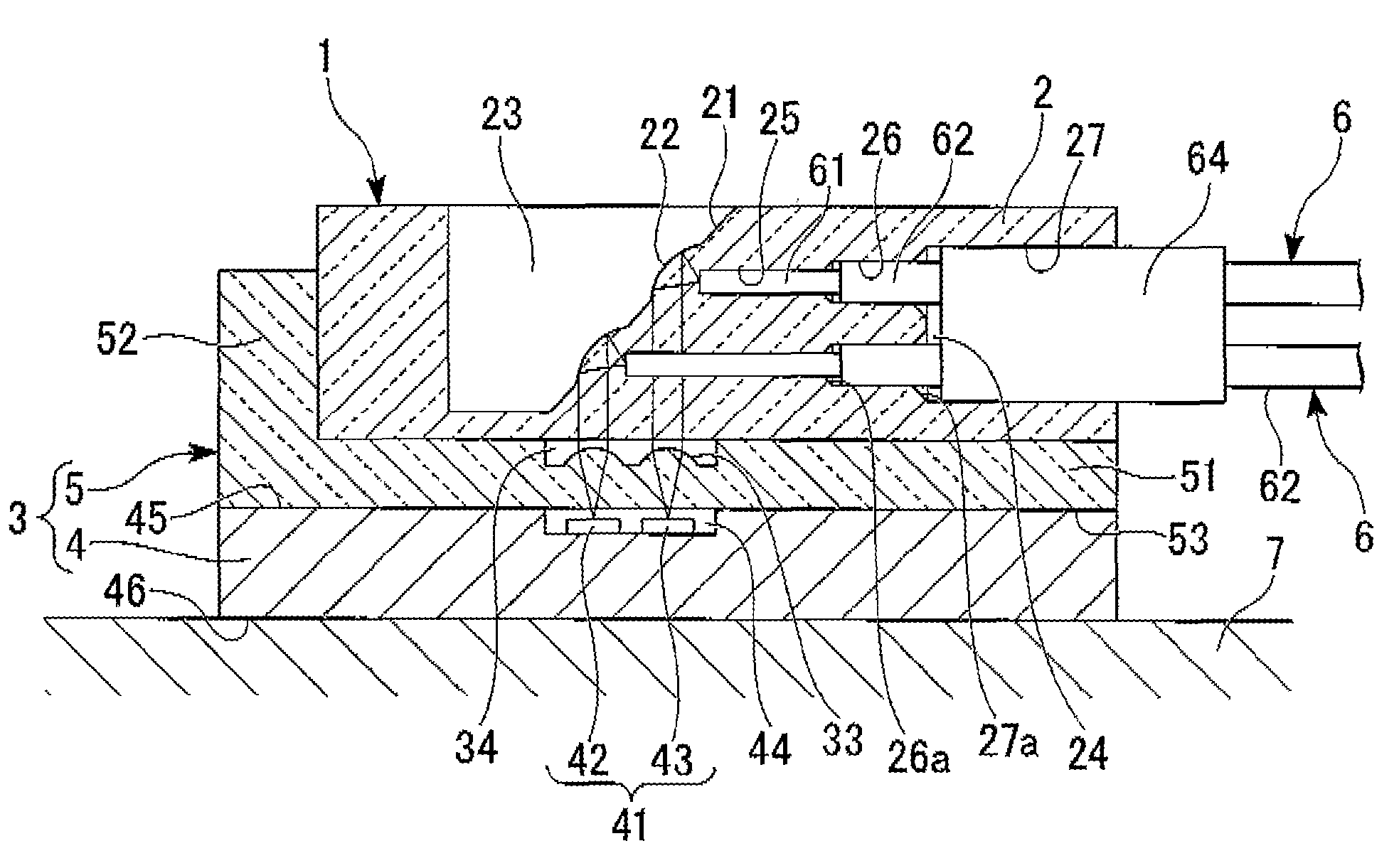
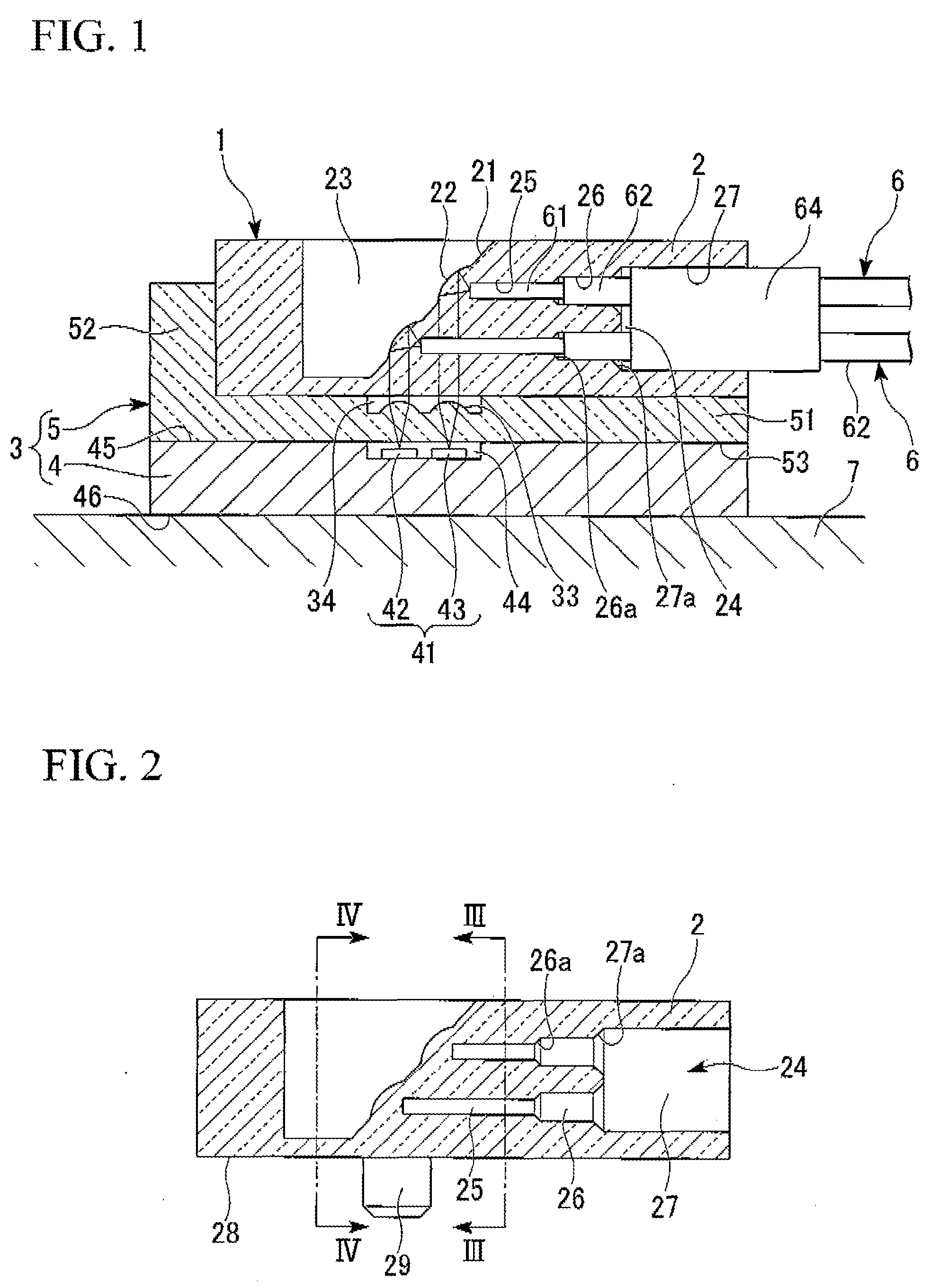
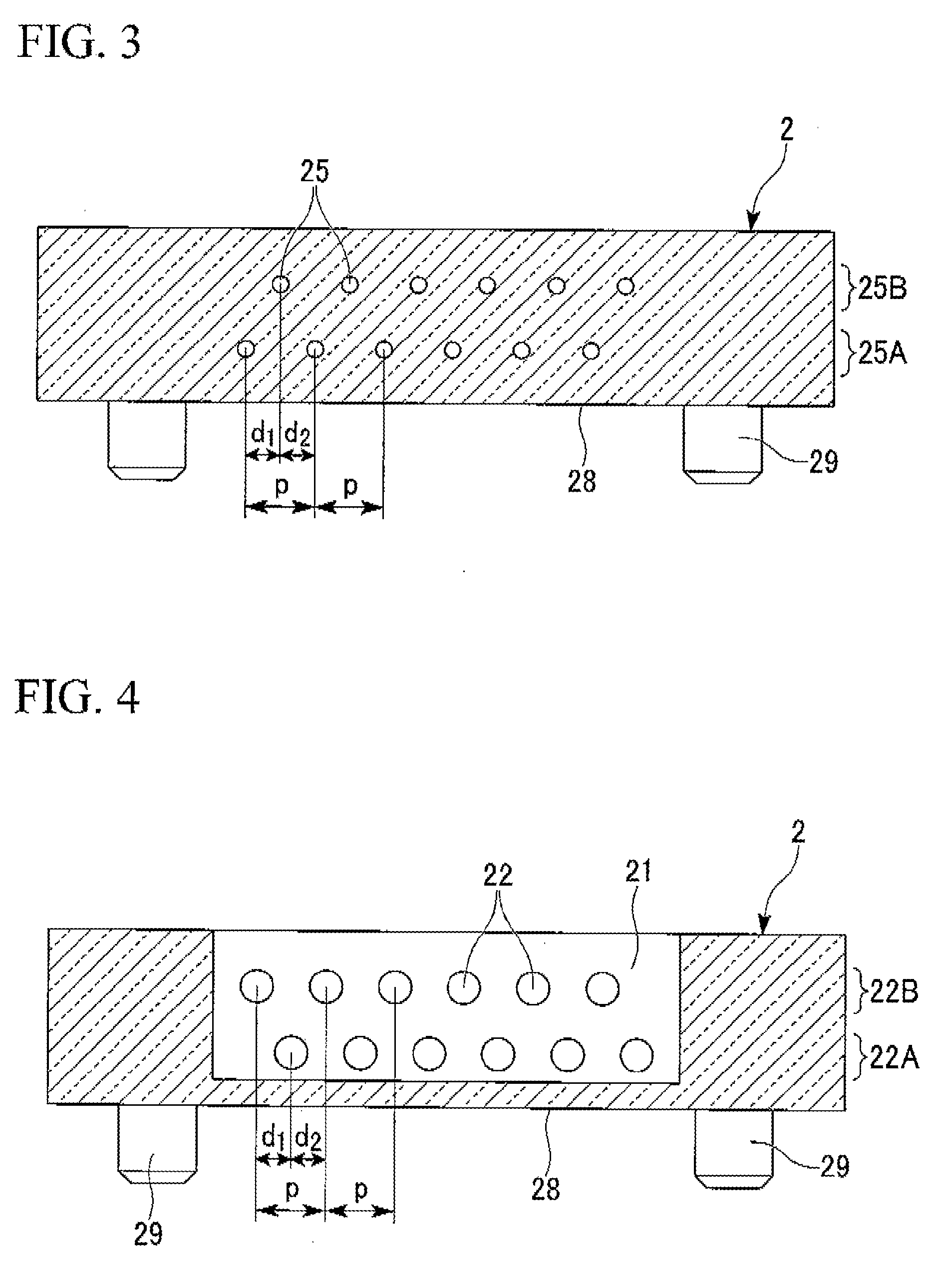
[0041]FIG. 1 is a cross-sectional view of an optical path change member 1 according to the first embodiment of the present invention. As shown in FIG. 1, a holding member body 2 provided at terminals of multi-core optical fibers 6 arranged in two rows is attached to an optical module 3 (board) having a light-emitting device 42 and a light-receiving device 43 mounted thereon. FIG. 2 is a cross-sectional view showing the holding member body 2 constituting the optical path change member 1 according to the first embodiment of the present invention. FIG. 3 is a cross-sectional view of the holding member body 2 taken along a line III-III in FIG. 2. FIG. 4 is a cross-sectional view of the holding member body 2 taken along a line IV-IV in FIG. 2. In FIG. 4, an arrangement of first lenses 22 formed on a reflective surface 21 provided in the optical path chang...

second embodiment

[0093]Hereinafter, a second embodiment of the present invention will be described.

[0094]While in the embodiment shown in FIGS. 3 and 4, the optical-fiber insertion holes 25 and the first lenses 22 are arranged in two rows, the optical-fiber insertion holes 25 and the first lenses 22 may be arranged in three or more rows according to the present invention.

[0095]When the optical-fiber insertion holes 25 are arranged in three or more rows, the positions of the optical-fiber insertion holes 25 are shifted from each other at least between adjacent ones of the rows. Accordingly, an interval between the optical fiber of the upper row and the optical fiber of the lower row is broadened, and thus, interference of noise or signal light can be prevented for an excellent optical connection.

[0096]FIG. 5 is a cross-sectional view of the holding member body 2 in which first lenses 22a are arranged in three rows as the multi-core optical fibers 6 are configured in three rows according to the second...

third embodiment

[0100]Hereinafter, a third embodiment of the present invention will be described.

[0101]FIG. 7 is a cross-sectional view showing an optical path change member 1A in which first lenses are not formed on a reflective surface 21A. The optical path change member 1A has the same configuration as the optical path change member 1 shown in FIG. 1 except that the first lenses are not formed on the reflective surface 21A of a holding member body 2.

[0102]The reflective surface 21A is allowed to be formed flat and optically connects multi-core optical fibers 6 with light input and output ends 41 using inner-surface reflection.

[0103]It is preferable that since parallelization of light by the first lenses is not performed in the optical path change member 1A, the optical paths 30 of optical fibers 61 have the same length to prevent beam diameters of lights of the optical, fibers 61 from being non-uniform. For example, it is preferable that optical paths 30A and 30B of optical fibers 61A and 61B in...


PUM


Abstract

Provided is an optical path change member including a holding member body formed of a transparent material. The holding member body includes: at least two rows of optical-fiber insertion holes which hold optical fibers inserted therein, such that the optical axes of the optical fibers are inclined with respect to an optical axis of the optical device, and a reflective inner surface which totally internally reflects light incident from the optical-fiber insertion holes to a surface of the holding member body configured to face an optical device on a board.

Description

BACKGROUND OF THE INVENTION[0001]1. Field of the Invention[0002]The present invention relates to an optical path change member provided at a terminal of a light transmission medium such as an optical fiber, and a holding member body used for the optical path change member. The optical path change member is an optical part for, changing an optical path direction between an optical fiber and a light input and output end provided on a board to optically connect the optical fiber with the light input and output end.[0003]Priority is claimed on Japanese Patent Application No. 2009-210376 filed on. Sep. 11, 2009, the disclosure of which is incorporated herein by reference.[0004]2. Description of the Related Art[0005]In recent years, a scheme of fixing an optical connector assembled with a front end portion of an optical fiber arranged along aboard, on the board to be optically connected to an optical device mounted on the board, such as a light-emitting device such as a vertical cavity su...

Claims


Application Information

Patent Timeline
IPC IPC(8): G02B6/32G02B6/26
CPCG02B6/425G02B6/4214
Inventor NISHIMURA, AKITO
Owner THE FUJIKURA CABLE WORKS LTD
Why Eureka
Try Eureka