In-vehicle charge and discharge control apparatus and partial control apparatus

a control apparatus and vehicle technology, applied in the direction of process and machine control, hybrid vehicles, instruments, etc., can solve the problem of inefficiency in accumulating energy, and achieve the effect of accumulating energy efficiently and avoiding the need or occurrence of cooling control

Inactive Publication Date: 2011-03-17
DENSO CORP
View PDF3 Cites 209 Cited by
  • Summary
  • Abstract
  • Description
  • Claims
  • Application Information

AI Technical Summary

Benefits of technology

[0013]It is an object of the present invention to provide a technology to enable the battery to efficiently accumulate energy in a battery restriction strengthening control which reduces an upper limit of an input and output power from a usual value when the battery, temperature becomes a battery upper limit temperature or greater.
[0017]Then, when the battery upper limit temperature reduction road range is completed and the estimate road range is entered, the battery upper limit temperature returns to the default value greater than the special value of the battery upper limit temperature. Thus, the battery temperature at the start point of the estimate road range (namely, at the end point of the battery upper limit temperature reduction road range) is controlled so as to be less than the special value of the battery upper limit temperature. After entering the estimate road range, even if the battery temperature rises by the estimated temperature increase, it does not reach the default value of the battery upper limit temperature, thereby eliminating the need or occurrence of the cooling control. Therefore, the battery restriction strengthening control is not executed, thereby not restricting an acquirable electric power amount from the regeneration. The battery is thus enabled to accumulate energy efficiently.

Problems solved by technology

Such a situation makes it impossible to accumulate energy efficiently.

Method used


Image

  • In-vehicle charge and discharge control apparatus and partial control apparatus
  • In-vehicle charge and discharge control apparatus and partial control apparatus
  • In-vehicle charge and discharge control apparatus and partial control apparatus

Examples


Embodiment Construction

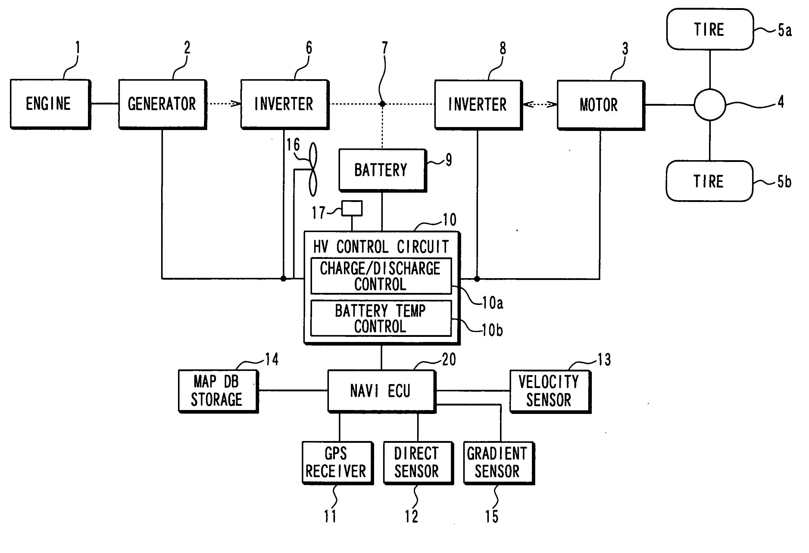
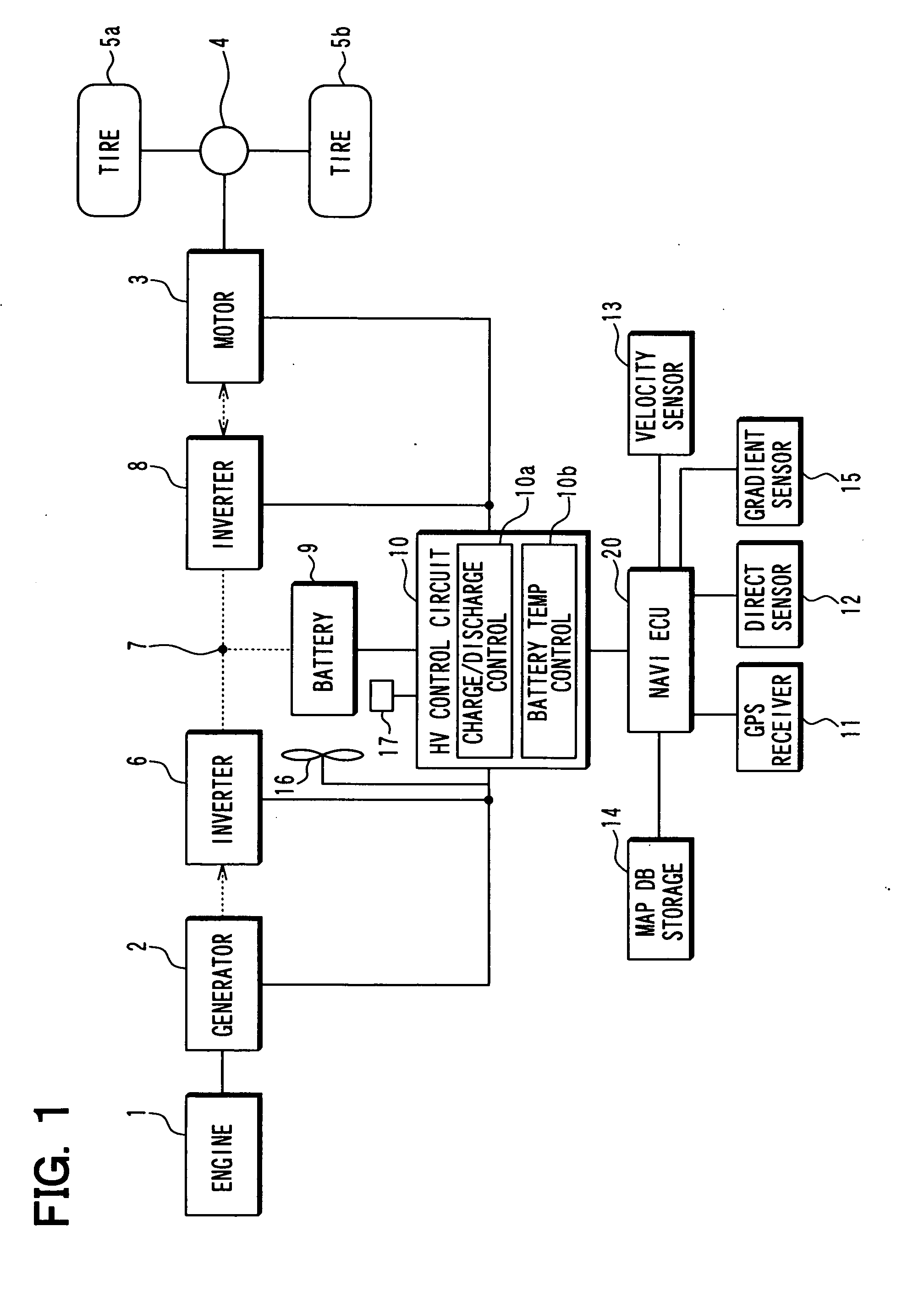
[0039]According to an embodiment of the present invention, an in-vehicle charge and discharge control apparatus of a hybrid vehicle is explained with reference to the drawings. The schematic configuration of the charge and discharge control apparatus is illustrated in FIG. 1. The hybrid vehicle includes an engine 1 as an internal-combustion engine, an electric generator 2, a motor 3, a differential gear device 4, tires 5a, 5b, an inverter 6, a DC link 7, an inverter 8, a battery 9, a HV (Hybrid Vehicle) control circuit 10, a battery cooling fan 16, a battery temperature sensor 17, a GPS receiver 11, a direction sensor 12, a vehicle velocity sensor 13, a map DB storage device 14, a gradient sensor 15, and a navigation ECU 20 (also serving as a partial control apparatus). The battery 9 uses a nickel hydoride battery.

[0040]The hybrid vehicle runs or travels using the engine 1 and the motor 3 as a power source for running or travel. When the engine 1 is used as the power source, a rotat...


PUM


Abstract

A temperature increase of a battery of a vehicle in a schedule effect road range is estimated based on an estimate of energy acquirable by regeneration in the schedule effect road range of the vehicle. A special value of the battery upper limit temperature is designated which is obtained by subtracting the temperature increase from a default value of the battery upper limit temperature. A battery upper limit temperature reduction road range is designated which is located just prior to the schedule effect road range. While the vehicle runs the battery upper limit temperature reduction road range, the battery upper limit temperature is set at the special value by being switched from the default value. When the vehicle completes running the battery upper limit temperature reduction road range and starts running the schedule effect road range, the battery upper limit temperature is returned to the default value from the special value.

Description

CROSS REFERENCE TO RELATED APPLICATION[0001]The present application is based on and incorporates herein by reference Japanese Patent Application No. 2009-210566 filed on Sep. 11, 2009.FIELD OF THE INVENTION[0002]The present invention relates to an in-vehicle charge and discharge control apparatus and a partial control apparatus contained in the same.BACKGROUND OF THE INVENTION[0003][Patent document 1] JP-2008-183937 A[0004][Patent document 2] JP-2000-333305 A (U.S. Pat. No. 6,314,347)[0005][Patent document 3] JP-2001-0.183150 A.[0006][Patent document 4] JP-2007-19687 A[0007][Patent document 5] JP-H11-195437 A[0008][Patent document 6] JP-2006-207539 A[0009]There is conventionally known an in-vehicle battery for supplying an electric power to an electronic apparatus such as a motor in the vehicle while accumulating an electric power which the above motor generates by regeneration at the time of deceleration of the vehicle (for example, refer to Patent documents 1 to 6).[0010]Such a ba...

Claims


Application Information

Patent Timeline
Patent Type & Authority Applications(United States)
IPC IPC(8): H02J7/00G06F7/00B60L50/13
CPCB60L7/16B60L1/00
Inventor SAKAI, TADASHIYAMADA, KAZUNAOMIZUNO, YUSUKE
Owner DENSO CORP
Why Eureka
Try Eureka