Traveling crane operation control apparatus and method

a technology of operation control and traveling crane, which is applied in the direction of electric/magnetic computing, instruments, analogue processes for specific applications, etc., can solve the problems of fine speed control of travel, traverse, lifting and lowering cannot be performed, etc., and achieves simple operation, lift or lower the traveling crane, and reduce the effect of siz

Active Publication Date: 2011-03-17
KITO CORP
View PDF6 Cites 24 Cited by
  • Summary
  • Abstract
  • Description
  • Claims
  • Application Information

AI Technical Summary

Benefits of technology

[0039]According to the present invention, the following advantageous effects can be obtained.
[0040](1) The operation control circuit section includes a base unit and a control unit, and a minimum number of pushbutton switches, including a variable-speed pushbutton switch, necessary for operation control are disposed on the control unit. Therefore, the control unit has a reduced size, and it is possible to perform operation control of the traveling crane by a simple operation without the need to gaze at the control unit.
[0041](2) The base unit tilt detecting means of the base unit worn on an arm detects a vertical tilt direction and angle of the base unit in a vertical plane, and the base unit direction detecting means of the base unit detects a direction in which the base unit points in a horizontal plane. Therefore, it is possible to move and lift or lower the traveling crane at a designated speed simply by pointing the base unit in a direction in which the traveling crane is desired to be moved and / or in a vertical direction in which the traveling crane is desired to be lifted or lowered, and operating the control unit. Accordingly, it is possible to perform fine and accurate speed and position control.
[0042](3) The operator can designate a moving direction and a lifting or lowering direction by a body motion with the base unit worn on his or her arm, head, waist, etc. Accordingly, the rotating range is large, and a desired direction can be finely designated.
[0043](4) Even when the base unit of the operation control circuit section is moved, none of travel, traverse, lifting and lowering motions of the traveling crane occur unless the control unit is operated to output a motion decision signal. Accordingly, accidental erroneous operation can be prevented, and thus safety can be ensured.

Problems solved by technology

There is another problem that fine speed control for travel, traverse, lifting and lowering cannot be performed.

Method used


Image

  • Traveling crane operation control apparatus and method
  • Traveling crane operation control apparatus and method
  • Traveling crane operation control apparatus and method

Examples


first embodiment

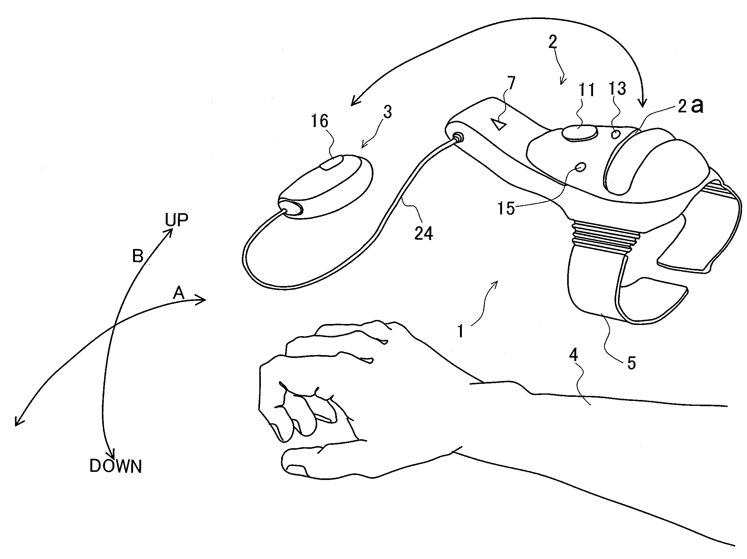
[0067]FIG. 3 is an external view showing a configuration example of an operation control circuit section of a traveling crane according to the present invention. The operation control circuit section 1 includes a base unit 2 and a control unit 3. The control unit 3 can be detachably fitted into a groove-shaped housing part 2a formed on the top of the base unit 2. The base unit 2 is wearable on an arm 4 by using an arm belt 5. The base unit 2 is provided with an emergency stop pushbutton switch 11, an indicator 7 comprising an LED (Light Emitting Diode) or the like to indicate that the apparatus is in operation, a reset pushbutton switch 13, and a power switch 15. The control unit 3 is provided with a motion decision variable-speed pushbutton switch 16.

[0068]With the operation control circuit section 1 arranged as stated above, an operator wears the base unit 2 on the arm 4 and holds the control unit 3 in the hand. In this state, the operator can press the motion decision variable-sp...

second embodiment

[0095]The external configuration of the traveling crane operation control circuit section in the second embodiment is the same as those shown in FIGS. 3 and 10, and the overall system configuration of the operation control apparatus is the same as that shown in FIG. 4; therefore, a description thereof is omitted. In the second embodiment, the method of operating the operation control circuit section 1 differs as follows. First, the operator wears the base unit 2 on the arm 4 and holds the control unit 3 in the hand in the same way as the first embodiment.

When only a travel-traverse operation is performed:

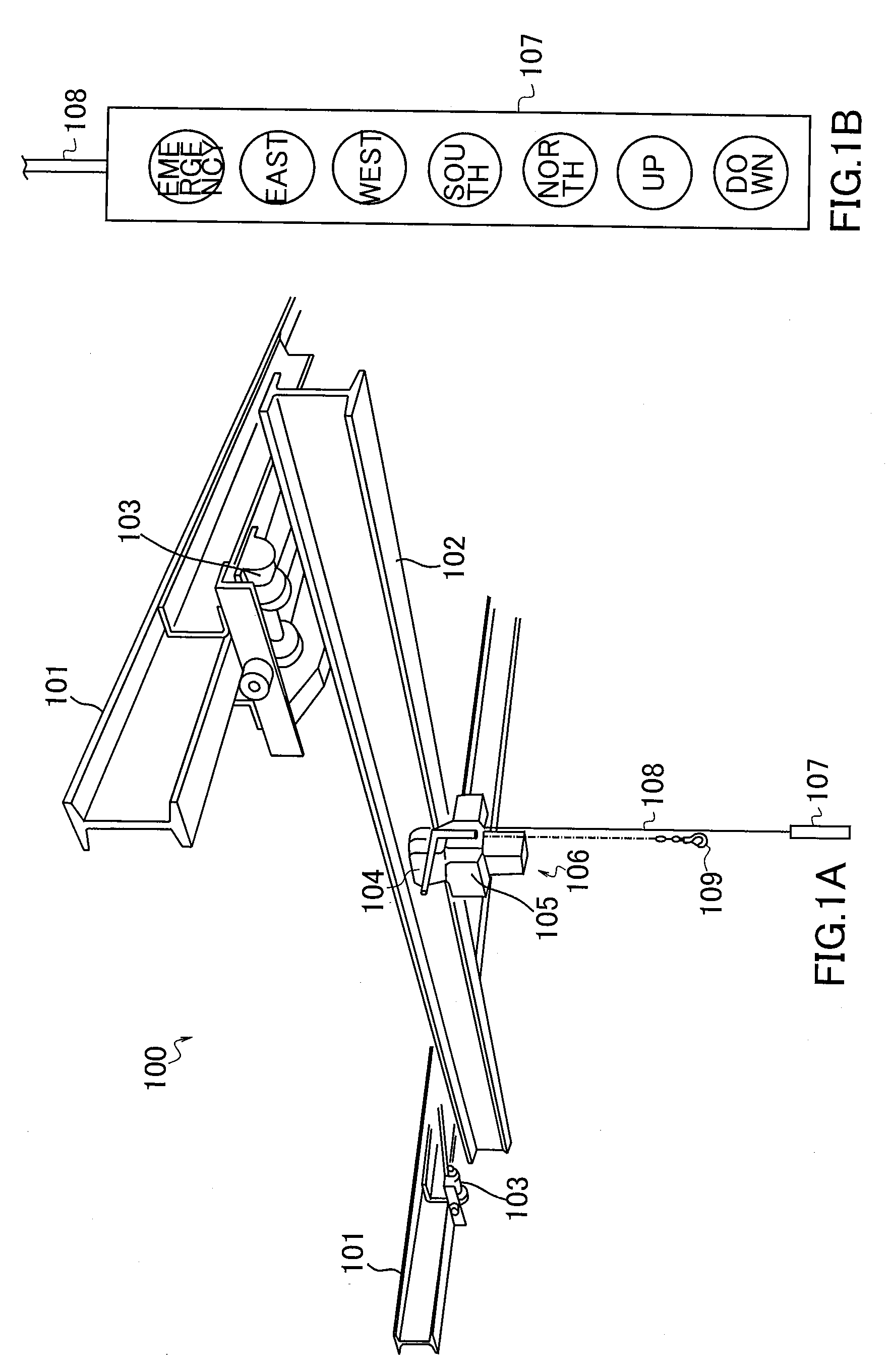
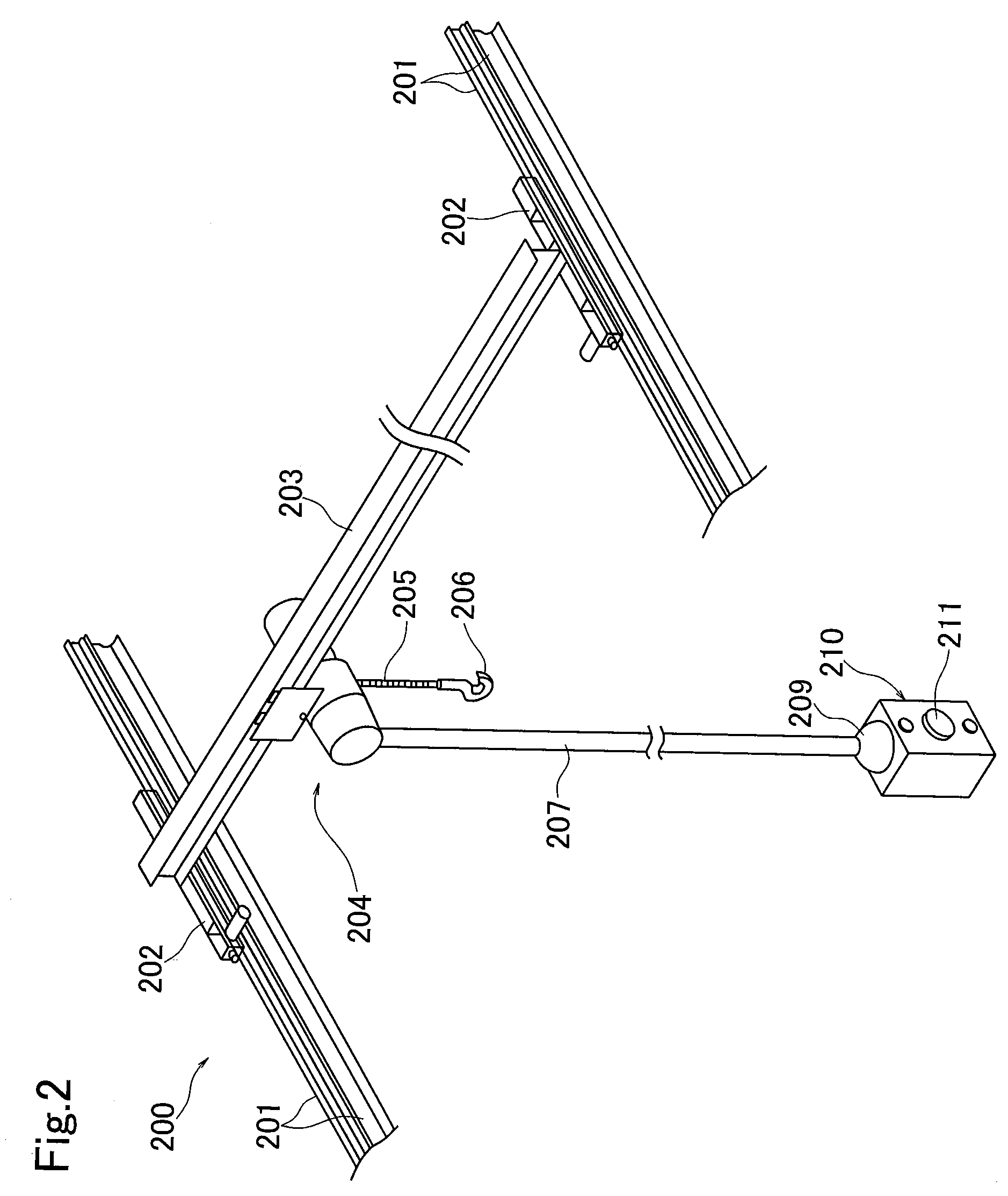
[0096]To move the electric hoist 106 or 204 (see FIGS. 1A and 2) in a predetermined direction in a horizontal plane, the operator, while keeping the arm 4 in a horizontal position (vertical tilt angle4 in a direction in which the electric hoist 106 or 204 is desired to be moved, and presses the motion decision variable-speed pushbutton switch 16 by a finger of the hand holding the c...

third embodiment

[0103]FIGS. 11 and 12 are external views showing configuration examples, respectively, of a traveling crane operation control circuit section according to a third embodiment. The external configuration of the operation control circuit section 1 of this embodiment differs from those shown in FIGS. 3 and 10 in that the operation control circuit section 1 has an elevation trigger pushbutton switch 17 provided on the control unit 3. FIG. 13 is a block diagram showing the overall system configuration of the operation control apparatus according to the third embodiment. As shown in the figure, the operation control apparatus differs from that shown in FIG. 4 only in that the control unit 3 is provided with an elevation trigger pushbutton switch 17. The block configurations of the base unit 2 and the motor drive control circuit section 30 are the same as those shown in FIG. 4.

[0104]With the traveling crane operation control circuit section of the above-described third embodiment, the opera...


PUM


Abstract

To provide a traveling crane operation control apparatus and method enabling an operator to operate a traveling crane quickly and accurately by one hand and by a motion of his or her body with a controller worn thereon, without the need to gaze at his or her hand, and also allowing variable-speed control and fine speed control of each drive unit.
An operation control apparatus for a traveling crane has an operation control circuit section 1 including a base unit 2 wearable on an arm 4 of an operator and a control unit 3 operable by a hand. The base unit 2 has base unit tilt detecting means detecting a tilt direction and tilt angle of the base unit 2 in a vertical plane, base unit direction detecting means detecting a direction in which the base unit 2 points in a horizontal plane, and command signal generating means generating a travel command signal and a travel speed command signal for a travel motor, a traverse command signal and a traverse speed command signal for a traverse motor, and an elevation command signal and an elevation speed command signal for an elevation motor. The traveling crane can be controlled to perform travel, traverse, lifting and lowering operations simply by pointing the base unit 2 in a direction in which travel and traverse motions are desired to occur and in a vertical direction in which a lifting or lowering motion is desired to occur, and actuating the control unit 3.

Description

TECHNICAL FIELD[0001]The present invention relates to an operation control apparatus and method for a traveling crane having a travel rail laid in a predetermined direction (e.g. east-west direction) in a horizontal plane, a traverse rail (girder) disposed in a direction (e.g. south-north direction) perpendicular to the travel rail and moved along the travel rail by a travel motor, and an electric hoist having a traverse motor for traversing along the traverse rail and an elevation motor for lifting and lowering a load.BACKGROUND ART[0002]FIG. 1A, FIG. 1B are a schematic external view showing a configuration example of the above-described traveling crane. The illustrated traveling crane 100 has travel rails 101 laid in a predetermined direction (e.g. east-west direction) in the horizontal plane of the ceiling of a building, a traverse rail (girder) 102 disposed in a direction (e.g. south-north direction) perpendicular to the travel rails 101 and moved along the travel rails 101 by g...

Claims


Application Information

Patent Timeline
Patent Type & Authority Applications(United States)
IPC IPC(8): B66C13/40G06F19/00B66C13/44
CPCB66C13/44B66C13/40
Inventor HASHIMOTO, TSUTOMUSHI, YAFANGFUKASAWA, MICHIOMURAMATSU, SHIGERUKOIZUMI, KOICHITERAI, SHIGEO
Owner KITO CORP
Why Eureka
Try Eureka