Welding apparatus for conveyor belts and method

Active Publication Date: 2011-03-24
FLEXIBLE STEEL LACING
View PDF23 Cites 30 Cited by
  • Summary
  • Abstract
  • Description
  • Claims
  • Application Information

AI Technical Summary

Benefits of technology

[0031]According to another aspect of the invention, a method for welding conveyor belt ends together is provides that includes supporting the belt ends in spaced relation from each other. The method also includes melting the material of the belt ends by operation of a heating device therebeween. Further the method includes providing a single actuator to sequentially shift the heating device and the belt ends by operating the single actuator to shift the heating device into the space between the belt ends, operating the single actuator to shift the heating device out from the space between the belt ends after the material of the belt ends is melted, and operating the single actuator to shift the belt ends toward each other to intermix the melted material. In this regard, an operator can operate the single actuator for a welding operation that joins the belt ends together. In this manner, an operator can conveniently join belt ends together using a single actuator and avoiding the need to manually insert and remove a heated bar from between the belt ends. In one form, the single actuator sequentially shifts the heating d

Problems solved by technology

In addition, the operator is not required to separate the belt ends and manually remove a heating bar, which requir

Method used


Image

  • Welding apparatus for conveyor belts and method
  • Welding apparatus for conveyor belts and method
  • Welding apparatus for conveyor belts and method

Examples


Embodiment Construction

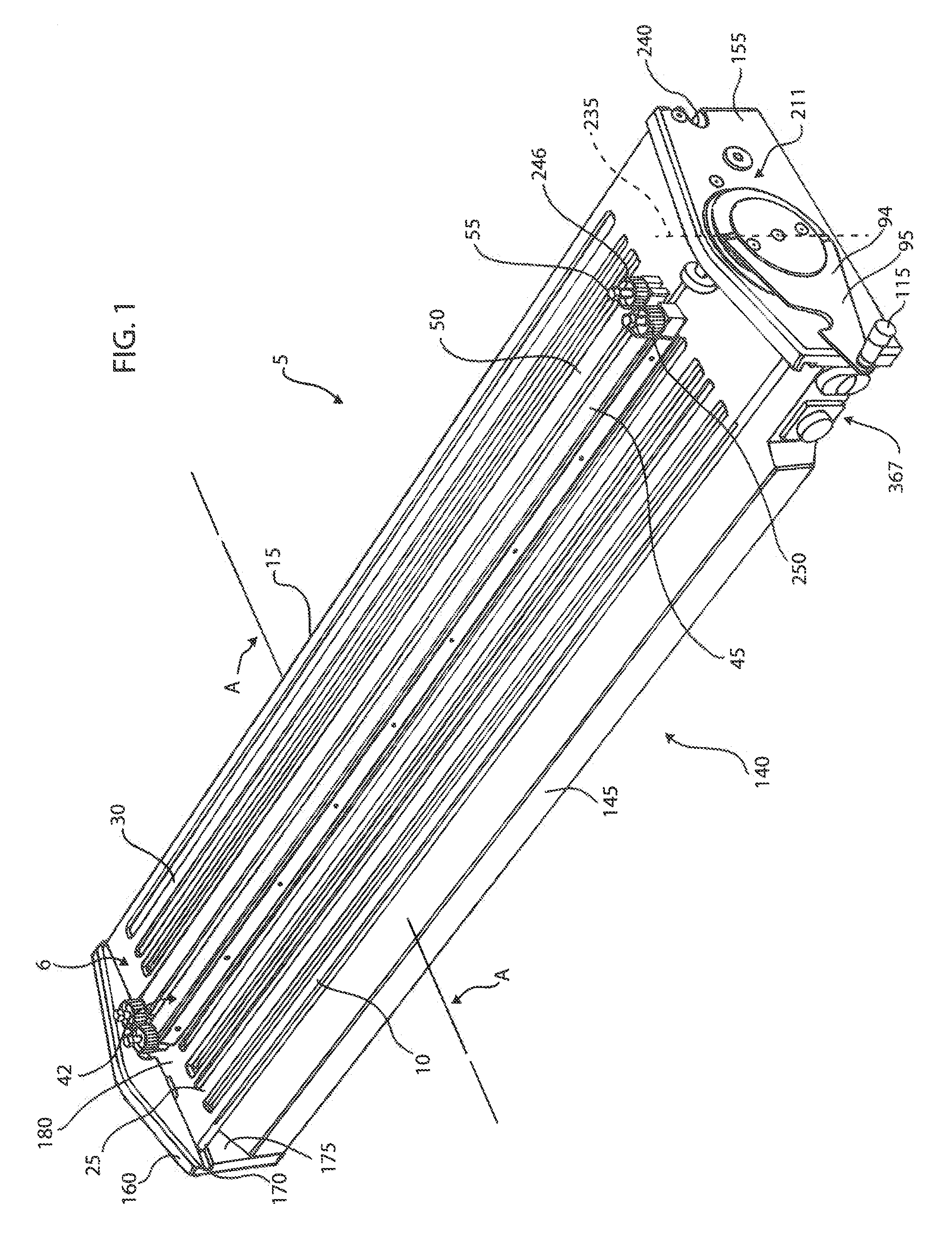
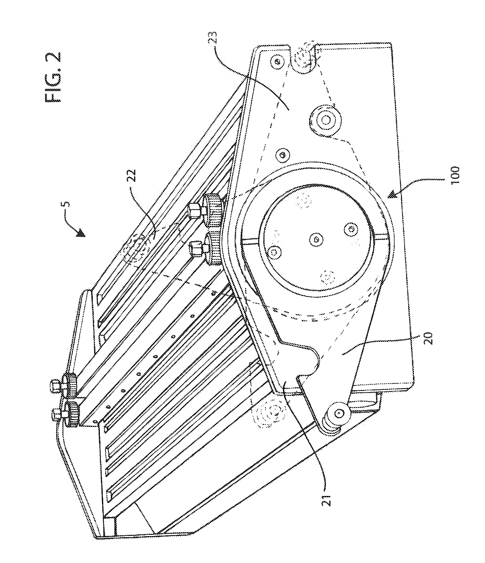
[0046]In FIGS. 1 and 2 a belt welding apparatus 5 in accordance with one form is illustrated, which includes a belt support 6 for positioning the ends 35 and 40 of one or more conveyor belts (FIG. 3) in spaced relation from each other and a heating device 70 for being disposed between the belt ends 35 and 40 for melting a portion of the material thereof. The belt support 6 may include a pair of elongate platens 10 and 15 extending side-by-side in a lengthwise direction across the lateral width of the belt ends 35 and 40 for supporting the belt ends thereabove. At least one of the platens 10 is preferably movable laterally with respect to the other platen 15 for moving one of the belt ends 35 toward and away from the other belt end 40. The belt positioning platens 10 and 15, and particularly upper surfaces 25 and 30 thereof, are substantially horizontal and coplanar with one another. In this respect, the conveyor belt ends 35 and 40 can be loaded on the upper surfaces 25 and 30 of th...


PUM

PropertyMeasurementUnit
Angleaaaaaaaaaa
Angleaaaaaaaaaa
Angleaaaaaaaaaa

Abstract

A belt welding apparatus is provided for joining together the ends of one or more monolithic conveyor belts. In one form, a belt support is configured to support the belt ends in spaced relation to each other and a non-contact heating device is provided for being disposed between the belt ends to generate thermal radiation for joining the belt ends together. In another form, a drive mechanism is operable to cause relative movement of a pair of platens, for supporting belt ends, toward and away from each other and a heating device between heating and stowed positions. An actuator of the drive mechanism is movable by an operator between at least three operation positions corresponding to three different operation positions of the platens.

Description

CROSS REFERENCES TO RELATED APPLICATIONS[0001]This patent claims benefit under 35 U.S.C. §119 (e) to U.S. Provisional Application No. 61 / 244,872 entitled “Infrared Vulcanizing Tool for Monolithic Belts” filed Sep. 22, 2009 having attorney docket number 6182 / 96868, the contents of which are incorporated herein by reference in its entirety.FIELD OF THE INVENTION[0002]The invention relates to an apparatus for joining together ends of one or more conveyor belts and, more particularly, to a welding apparatus for forming a weld between the ends of one or more monolithic conveyor belts.BACKGROUND OF THE INVENTION[0003]Several industries utilize conveyor and process belts for transporting loads from one location to another location or for passing loads through successive processing operations. Many of these applications require conveyor belts that are able to maintain cleanliness under various and sometimes harsh conditions. For example, in the food and dairy industries, conveyor belts shou...

Claims


Application Information

Patent Timeline
IPC IPC(8): B29C65/02B29C65/14
CPCB29C65/1412B29C65/1432B29C65/782B29C65/7844B29C66/1142B29C66/5241F16G3/003F16G3/10F16G3/16B29C66/4322B29C66/49B29C66/4324B29C65/20B29C65/7841B29C66/73921B29C66/8226B29C66/855B29L2031/7092
Inventor VAN 'T SCHIP, JOANNES STEFANUS
Owner FLEXIBLE STEEL LACING
Why Eureka
Try Eureka