Flow controller device

Inactive Publication Date: 2011-03-24
BECH WELLBORE FLOW CONTROL
View PDF24 Cites 35 Cited by
  • Summary
  • Abstract
  • Description
  • Claims
  • Application Information

AI Technical Summary

Benefits of technology

[0026]The flow controller is also suitable for use in vertical or near-vertical wells, which oftentimes may penetrate several reservoir layers of dissimilar permeabilities, viscosities and reservoir pressures, insofar as the flow controllers may be set so as to be able to maximize the recovery from all layers.
[0027]During the production time of a petroleum well, th

Problems solved by technology

In wells of relatively long penetration into a reservoir, so-called uneven production easily occurs.
If this inflow is not controlled, the production will be uneven, which may lead to water or gas coning.
As the pressure in the reservoir changes, the r

Method used


Image

  • Flow controller device
  • Flow controller device
  • Flow controller device

Examples


Embodiment Construction

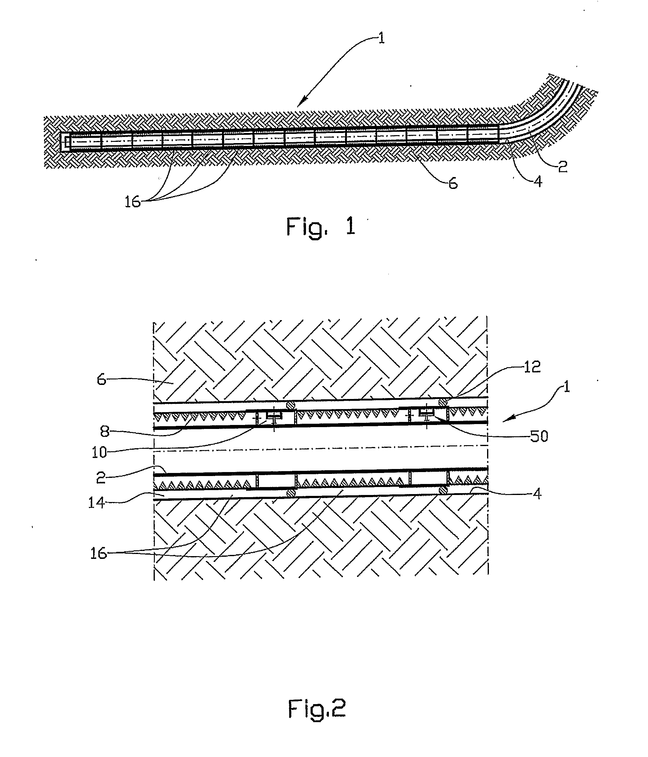
[0036]In the drawings, reference numeral 1 denotes a petroleum well having a pipe body 2 in the form of a production tubing disposed within a borehole 4 in a reservoir 6.

[0037]The pipe body 2 is provided with completion equipment in the form of sand screens 8 and inflow chambers 10, see FIG. 2.

[0038]A number of packers 12 are arranged in an annulus 14 between the sand screen 8 and the borehole 4, dividing the well 1 into a number of sections 16.

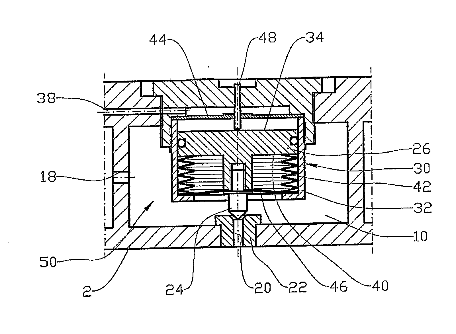
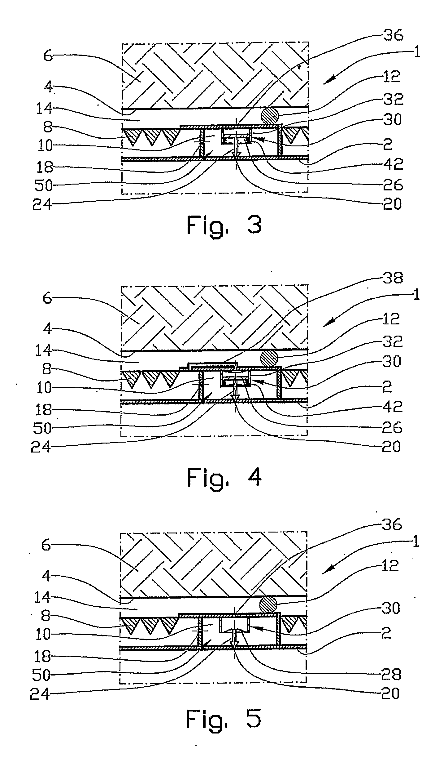
[0039]Well fluid flows via the sand screen 8 and a flow restriction 18 in the form of a nozzle, see FIGS. 3 to 6, into the inflow chamber 10 and further through a valve opening 20 and into the pipe body 2. The flow restriction 18 may be adjustable.

[0040]The valve opening 20 is located in a valve seat 22 cooperating with a valve body 24, see FIG. 6. The valve body 24 is connected to a piston 26, see FIGS. 3, 4 and 6, or to a diaphragm 28, see FIG. 5, in an actuator 30.

[0041]Should the actuator 30 be provided with a piston 28, the piston 26 is ...


PUM


Abstract

A flow controller device (50) for controlling a fluid flow between a petroleum reservoir (6) and a pipe body (2), in which the fluid flow is carried through a flow restriction (18), and a pressure-controlled actuator (30) is connected to a valve body (24) cooperating with a valve opening (20) connected in series relative to the flow restriction (18), wherein the actuator (30), on a closing side (34) thereof, communicates with fluid located upstream of the valve opening (20) and the flow restriction (18), and wherein the actuator (30), on an opening side (40) thereof, communicates with a fluid located downstream of the flow restriction (18) and upstream of the valve opening (20).

Description

FIELD OF THE INVENTION[0001]A flow controller is provided. More particularly, it involves a flow controller for controlling a fluid flow between a petroleum reservoir and a pipe body, in which the carried through a flow restriction.BACKGROUND OF THE INVENTION [0002]In wells of relatively long penetration into a reservoir, so-called uneven production easily occurs. This implies a dissimilar inflow of reservoir fluid along the well. The situation is mainly due to a pressure drop in the production tubing, and is particularly common in horizontal or near-horizontal wells.[0003]In many of the wells, also in vertical or near-vertical wells, the situation may be due to dissimilar permeability, viscosity or pore pressure in different zones of the well.[0004]The conditions underlying the invention are explained hereinafter with reference to a horizontal well. This does not limit the scope of the invention in any way.[0005]Oftentimes, the inflow into the production tubing is substantially lar...

Claims


Application Information

Patent Timeline
IPC IPC(8): E21B34/00
CPCE21B34/08E21B43/32E21B43/12
Inventor AADNOY, BERNT SIGVE
Owner BECH WELLBORE FLOW CONTROL
Why Eureka
Try Eureka