Mechanical-electric-hydraulic compound braking system and corresponding vehicle

A compound braking, electro-mechanical-hydraulic technology, applied in the field of vehicles, can solve the problems of high overall cost, abnormal function of ABS and ESP, and high integration requirements, and achieve a safety hazard, abnormal function, integration and function enhancement. Effect

Active Publication Date: 2013-08-28
千顾汽车科技(江苏)有限公司
View PDF5 Cites 26 Cited by
  • Summary
  • Abstract
  • Description
  • Claims
  • Application Information

AI Technical Summary

Problems solved by technology

[0004] At present, this type of braking system is a design structure commonly used by passenger cars all over the world. Its advantages are stable and reliable, and its design is mature. high
In addition, with the development of vehicle technology and increasingly stringent vehicle environmental protection and emission requirements, this type of braking system has increasingly shown its shortcomings that are not suitable for the development requirements of the times, mainly reflected in two points: first, engine technology The increasing emphasis on environmental protection and fuel economy has led to the improvement of its air intake efficiency and the corresponding decrease in vacuum degree, which is increasingly unable to meet the requirements of brake vacuum boosting. Although some vehicles have begun to be equipped with mechanical vacuum pumps, since the mechanical vacuum pump is a functional accessory of the engine , requires the engine to drive, which instead increases the load on the engine and has a greater impact on fuel consumption, which is contrary to the principle of energy conservation and environmental protection, so it cannot be adopted and popularized by all vehicle designers; With the increasing emphasis on energy vehicles and the rapid development of related technologies, high-power driving motors have begun to be equipped on new energy vehicles. The biggest feature of this type of motor is that it can recover energy and generate electricity when the vehicle has the intention to decelerate, so as to realize the braking energy. Recycling, but at present, due to the existence of the traditional hydraulic braking system, there are two modes of traditional hydraulic braking and motor braking at the same time when the vehicle is decelerating and braking, which seriously affects the normal driving of the driver, especially in low adhesion Under the condition of the road surface, it will lead to the abnormal function of ABS and ESP, and there is a great potential safety hazard

Method used


Image

  • Mechanical-electric-hydraulic compound braking system and corresponding vehicle
  • Mechanical-electric-hydraulic compound braking system and corresponding vehicle

Examples


Embodiment Construction

[0021] In the following, specific embodiments of the present invention will be described in more detail with reference to the accompanying drawings in order to better understand the basic idea of ​​the present invention.

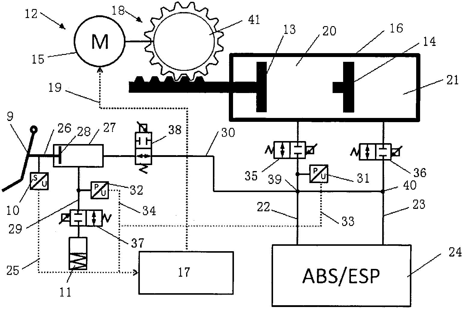
[0022] figure 2 A simplified diagram of a fully decoupled electromechanical hydraulic brake system according to an exemplary embodiment of the present invention is shown.

[0023] Such as figure 2 As shown, the fully decoupled electromechanical-hydraulic brake system mainly includes: an electronically controlled linear motion module 12 , a booster master cylinder 16 , a pedal simulator 11 and a brake pedal 9 . The brake pedal 9 is equipped with a displacement sensor 10 which makes it possible to determine the velocity and displacement of the brake pedal 9 when it is depressed.

[0024] In this exemplary embodiment, the electronically controlled linear motion module 12 includes an electronic control unit 17 and a linear motion mechanism 18 . The electron...


PUM


Abstract

The invention discloses a mechanical-electric-hydraulic compound braking system for a vehicle. The mechanical-electric-hydraulic compound braking system comprises a braking pedal, a sensor, a boosting main cylinder, an electrically-controlled linear motion module and a pedal simulator, wherein the braking pedal is used for acquiring the speed and the displacement when the braking pedal is stepped down; the boosting main cylinder is hydraulically coupled with a wheel-edge brake device by a first electrically-controlled valve; the electrically-controlled linear motion module is directly connected with the boosting main cylinder and is suitable for driving a piston of the boosting main cylinder to do linear motion by signals from the sensor; the pedal simulator is hydraulically coupled with the braking pedal by a second electrically-controlled valve; the braking pedal is hydraulically coupled with the wheel-edge brake device of the vehicle by a third electrically-controlled valve; the first electrically-controlled valve and the second electrically-controlled valve are manufactured to be suitable for simultaneous opening and closing; and the third electrically-controlled valve is manufactured to be suitable for keeping closed when the first electrically-controlled valve and the second electrically-controlled valve are opened. The mechanical-electric-hydraulic compound braking system disclosed by the invention has the advantages that the structure is simple, the full decoupling is realized, and the integration degree and the function of the system are greatly enhanced.

Description

technical field [0001] The invention relates to an electromechanical-hydraulic composite braking system and a vehicle including the electromechanical-hydraulic composite braking system. Background technique [0002] At present, the braking system on automobiles is divided according to the type of vehicle, mainly divided into hydraulic braking system and pneumatic braking system. Generally, passenger cars with low weight adopt hydraulic braking system. Conventional vacuum assisted hydraulic brake systems such as figure 1 As shown, it is mainly composed of pedal 2, vacuum booster 3, master cylinder 5, liquid storage tank 4, ABS (anti-lock braking system) / ESP (dynamic stability control system) module 6 and wheel brake 8, and vacuum booster 3 The required vacuum is mainly provided by vacuum sources such as the engine 1 and the vacuum pump 7, and a total of five assembly modules realize the function of the braking system. When the driver of the passenger car brakes, by stepping...

Claims


Application Information

Patent Timeline
Patent Type & Authority Applications(China)
IPC IPC(8): B60L7/10B60T13/12
CPCB60T8/4081
Inventor 陈晶杰徐松云
Owner 千顾汽车科技(江苏)有限公司
Why Eureka
Try Eureka