Scaffold Element, Arrangement and Method of Use

a technology of scaffold element and arrangement, applied in the direction of scaffold accessories, bridges, building scaffolds, etc., can solve the problems of difficult mounting, damage to the edge structure, and disturbing the road traffic and often also the railway traffic of the bridge with lifting machines

Inactive Publication Date: 2011-03-24
MOLDTECH OY
View PDF16 Cites 13 Cited by
  • Summary
  • Abstract
  • Description
  • Claims
  • Application Information

AI Technical Summary

Benefits of technology

[0006]One objective of the invention is to disclose a scaffold element which can be easily mounted so that as short working period as possible from underneath the bridge is required. A further objective of the invention is to disclose a method and an arrangement which enable a considerably faster repair of the edge structure of a bridge compared to the present situation.
[0009]Still yet another objective of the invention is to disclose a scaffold element and arrangement that allows easy setup and adjustment of vertical mould walls that may have e.g. a curved shape.SUMMARY OF THE INVENTION
[0039]An aspect of the invention is a method of installing the scaffold element onto a bridge. When installing the scaffold element onto a bridge, the support structure of the scaffold element is fixedly anchored by at least one support member to the upper surface of the bridge at a distance from the edge of the bridge that needs repairing. This method provides the advantage that the scaffold element can be mounted by working from the top of the bridge, which reduces considerably the time required for the repair work. The scaffold element is quickly mounted and disassembled, saving costs and reducing the traffic disturbance. The scaffold element is safe for those trafficking below. There is no disturbance for the traffic below the bridge. There is little or no need to drill thorough holes into the deck of the bridge that would later have to be patched up. Being advantageously metal-structured, the arrangement is strong and it can be used repeatedly several times all over again in different locations and be adapted and adjusted to be suitable for almost all existing bridges.
[0044]In one embodiment of the method, the first vertical mould wall is first attached to the holding members of first and third scaffold elements and then attached to the holding members of a second scaffold element residing between the first and third scaffold elements. The adjustment screws of the second scaffold element are then used to bend the vertical mould wall by pushing or pulling the mould wall. This way the mould wall may be conveniently installed and adapted to form a curve that e.g. matches the curved form of a bridge.

Problems solved by technology

The edge structure is also susceptible to damage over time e.g. due to disintegration of the concrete, providing a need to repair the edge structure.
The problem with all known scaffold arrangements is that in order to provide a sufficiently tight mounting, the mounting of the scaffold has required the formation of holes extending through the entire deck of the bridge.
Long-term work on / under the bridge with lifting machines disturbs road traffic and often also railway traffic.
Moreover, the mounting is difficult in bridges which cross waterways.
With the known methods and arrangements, for example the construction of a scaffold arrangement required for repairing the edge beam of a bridge has taken a long time.
Long mounting and repair periods hinder the traffic and increase the expenses.
Furthermore, the present scaffolds are usually made of timber, so that the scaffolds are disassembled after the work is completed, and only a portion of the stouter timber may be reused, the rest ending up on a landfill site as unserviceable.

Method used


Image

  • Scaffold Element, Arrangement and Method of Use
  • Scaffold Element, Arrangement and Method of Use
  • Scaffold Element, Arrangement and Method of Use

Examples


Embodiment Construction

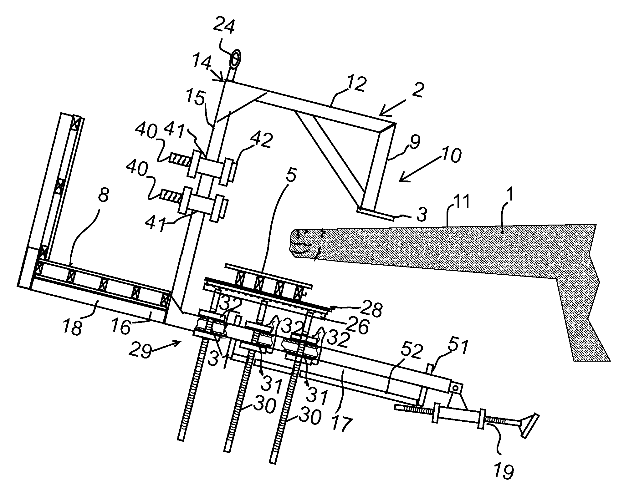
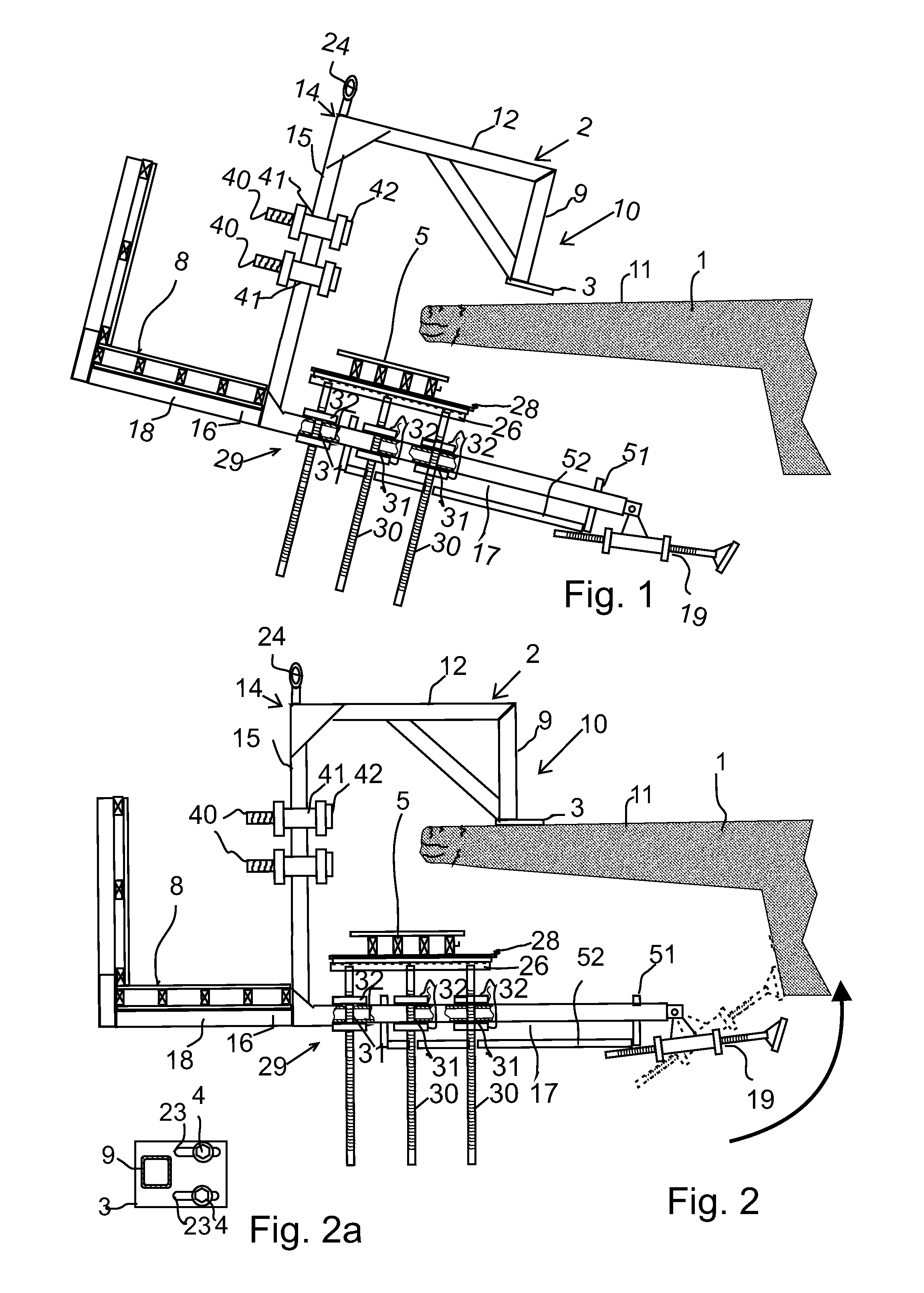
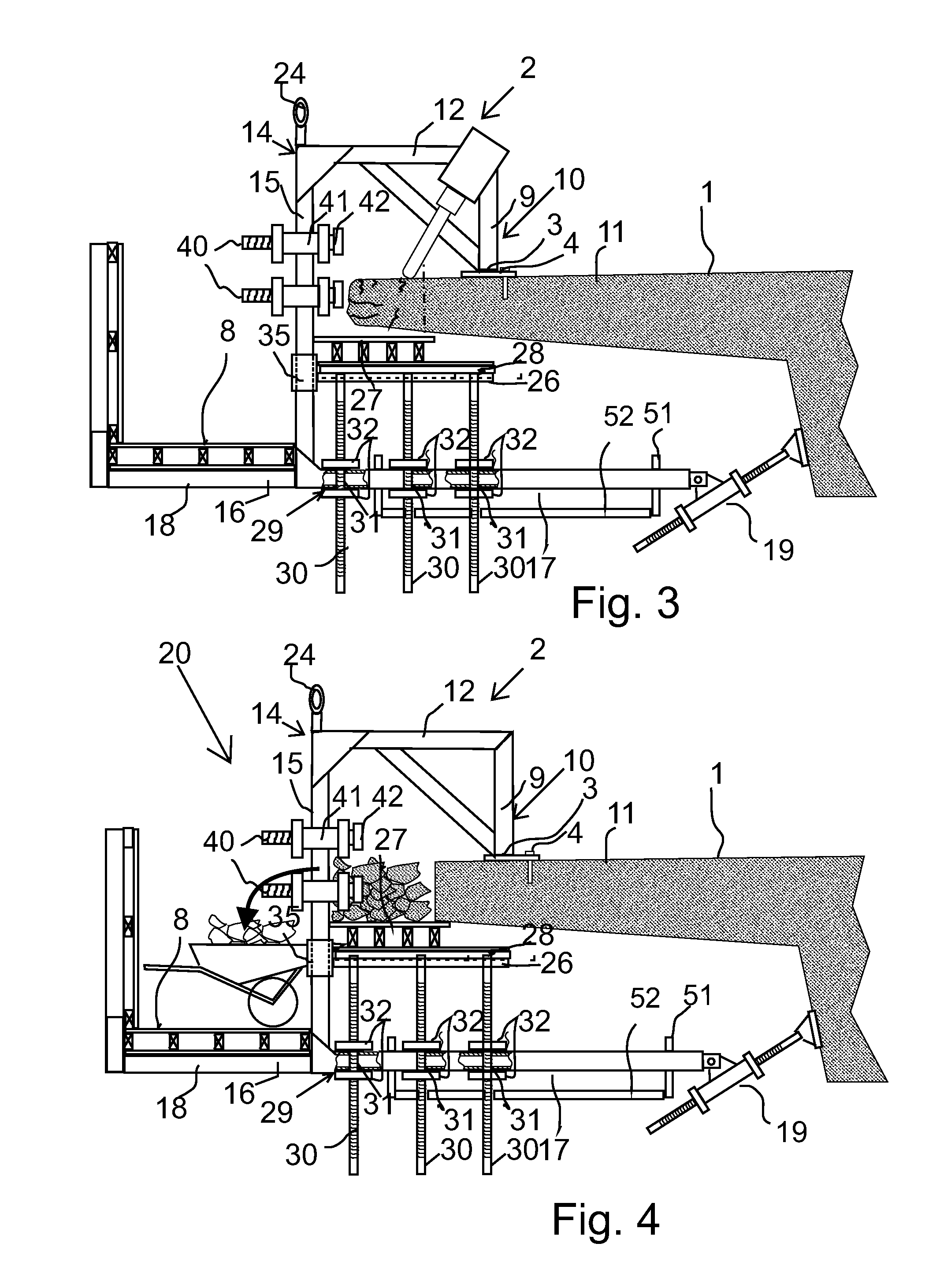
[0058]FIG. 1-10 show the scaffold element to be mounted on the upper surface of a concrete bridge in order to repair a concrete edge structure of the bridge. FIG. 1-9 show the bridge in cross-section. As seen from the side view 10, in the arrangement a number of scaffold elements 2 are arranged at a distance from each other along the length of the portion of the bridge that needs to be repaired. For example when renewing the edge beam of the bridge or broadening the deck of the bridge, the scaffold arrangement is usually constructed to extend over the entire length of the bridge.

[0059]FIG. 1-9 show one scaffold element 2. Suitably, all elements 2 in the arrangement are identical.

[0060]The scaffold elements 2 are supported by support members 3, 4 onto the upper surface close to the edge of the bridge, as will be described below. Mould walls 5, 6, 7 can be supported onto the scaffold elements 2 to form a concrete casting mould for casting a new edge structure for the bridge. The scaff...


PUM


Abstract

The invention concerns a scaffold element adapted to be removably attachable to a bridge, the scaffold element comprising support member for supporting the scaffold element onto an upper surface of the bridge and a support structure which is secured to the support members and which extends to a distance outside the edge of the bridge and to a distance below the bridge. The invention is characterized in that the scaffold element further comprises a longitudinally adjustable support bar pivotally connected to the support structure and being supportable against a lower surface of the bridge and adjustment means for adjustably attaching a vertical mould wall onto the support structure of the scaffold element at a distance outside the edge of the bridge for forming a mould between the wall and the bridge. Also a scaffold arrangement and method of use are disclosed.

Description

FIELD OF THE INVENTION[0001]The invention relates to a scaffold element, arrangement and method of use of such element and arrangement.BACKGROUND OF THE INVENTION[0002]The edge structure, such as the edge beam, of a concrete bridge is often built separately after constructing the deck of the bridge. There thus is a need for a scaffold usable for building the edge structure. The edge structure is also susceptible to damage over time e.g. due to disintegration of the concrete, providing a need to repair the edge structure.[0003]The closest prior art is represented by a scaffold arrangement comprising a casting mould and an access bridge supported onto the same scaffold that is suspended from the edge of the bridge. The arrangement comprises a number of bents arranged at a distance from each other for the length of the area of the bridge that needs repairing and supported onto the edge of the bridge by support members. The access bridge is supported onto the bents in order to form a pa...

Claims


Application Information

Patent Timeline
Patent Type & Authority Applications(United States)
IPC IPC(8): E01D22/00E04G3/24E04G5/04
CPCE01D19/10E04G13/06E04G3/24E01D22/00E04G13/066
Inventor JORKAMA-LOPEZ, TOMASOJANTAUSTA, HANNU
Owner MOLDTECH OY
Why Eureka
Try Eureka