
Slot sieve and holding device for the production thereof

a technology of slot sieve and holding device, which is applied in the direction of screening, stationary filter element filter, and screening, can solve the problems of general change of slot width, practicable bend about curvature extending parallel to the longitudinal axes of the carrier profile, etc., and achieve the effect of improving the ratio of the open area of the sieve to the total area

Inactive Publication Date: 2011-03-24
ZOLLNER THORSTEN
View PDF2 Cites 5 Cited by
  • Summary
  • Abstract
  • Description
  • Claims
  • Application Information

AI Technical Summary

Benefits of technology

[0012]Because of this positioning of the carrier profiles, these are located within the enveloping plane spanned by the slot sides or lower sides remote therefrom of the sieve profiles, so the slot sieves have level outline faces on their two flat sides. Bending tools in the form of roller pairs can thus engage thereon without problems and shape the slot sieves accordingly about axes of curvature oriented virtually in any desired manner into a trough-shaped configuration. A further advantage of the slot sieves according to the invention is the fact that the ratio of the open area to the total area of the sieve can be significantly improved compared to conventional slot-milled slot sieves. An increase from, for example, 9% to 17% open area fraction is typical.
[0014]Owing to the preferred embodiment, in which the sieve profiles have a respective trapezoidal cross section, at least in their profile region facing the sieve slot, their wide base sides forming the slot side of the respective sieve profile, the sieve profiles have a wide base, which can be connected in a particularly stable manner to the carrier profiles let into these sides. This benefits the robustness of the sieves according to the invention.
[0019]An arrangement of narrower lamellar intermediate webs, which are held by the carrier profiles and form a sieve slot with the respective adjacent sieve profile, between the sieve profiles, and a configuration of the intermediate webs as flat metal sheets, the narrow longitudinal sides of which are located in a plane with the slot sides of the sieve profiles, characterise preferred developments, in which narrower, lamellar intermediate webs are arranged between the sieve profiles. These are preferably configured as flat metal sheets, the narrow longitudinal sides of which are located in a plane with the slot sides of the sieve profiles. The ratio of the open area of the sieve to the total area can be again improved with the aid of these intermediate webs. The reason for this is that the narrow longitudinal sides of the intermediate webs are significantly narrower than the base sides of the sieve profiles, so that merely owing to the small area requirement of the web narrow sides, a doubling of the sieve slot and therefore of the open area of the sieve can be achieved.

Problems solved by technology

The problem in the two variants mentioned above of previously known slot sieves is the fact that the transversely extending carrier profiles extend outside the area plane spanned by the sieve profiles.
As slot sieves of this type are now often used in a configuration curved about an axis, as so-called sieve troughs, the difficulty is produced from the presence of the described carrier profiles that sieves of this type can only be curved around an axis extending transverse to the carrier profiles.
A bend about axes of curvature extending parallel to the longitudinal axes of the carrier profiles is practically not possible as the conventionally used bending roller pairs do not find any uniform thickness of the slot sieves in the rolling direction because of the projecting carrier profiles.
A further drawback in the known slot sieve is that the slot widths generally change when a sieve is bent as the carrier profiles are spaced apart from the actual sieve plane of the slot sieve spanned by the sieve slots.

Method used


Image

  • Slot sieve and holding device for the production thereof
  • Slot sieve and holding device for the production thereof
  • Slot sieve and holding device for the production thereof

Examples


Embodiment Construction

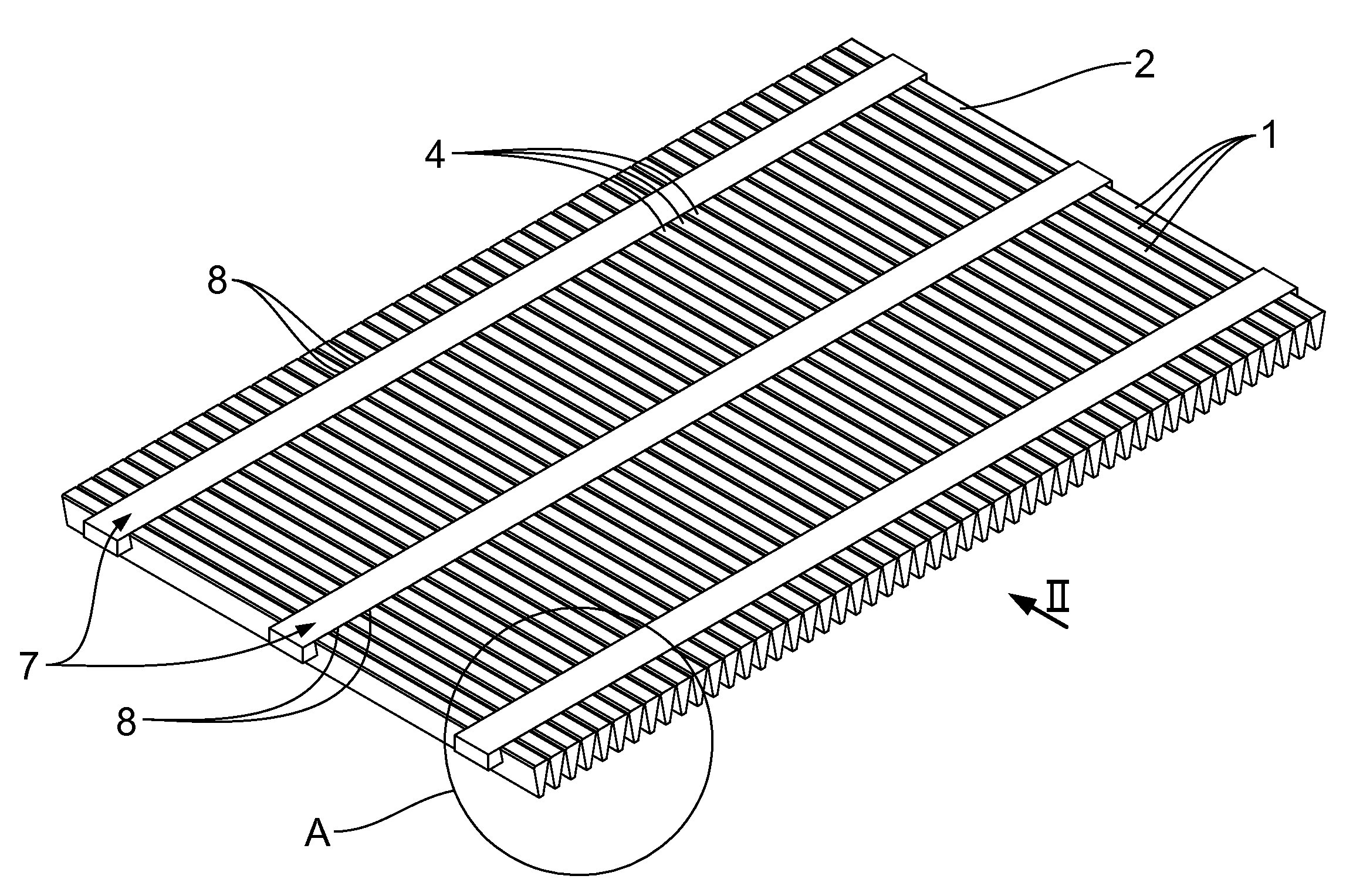
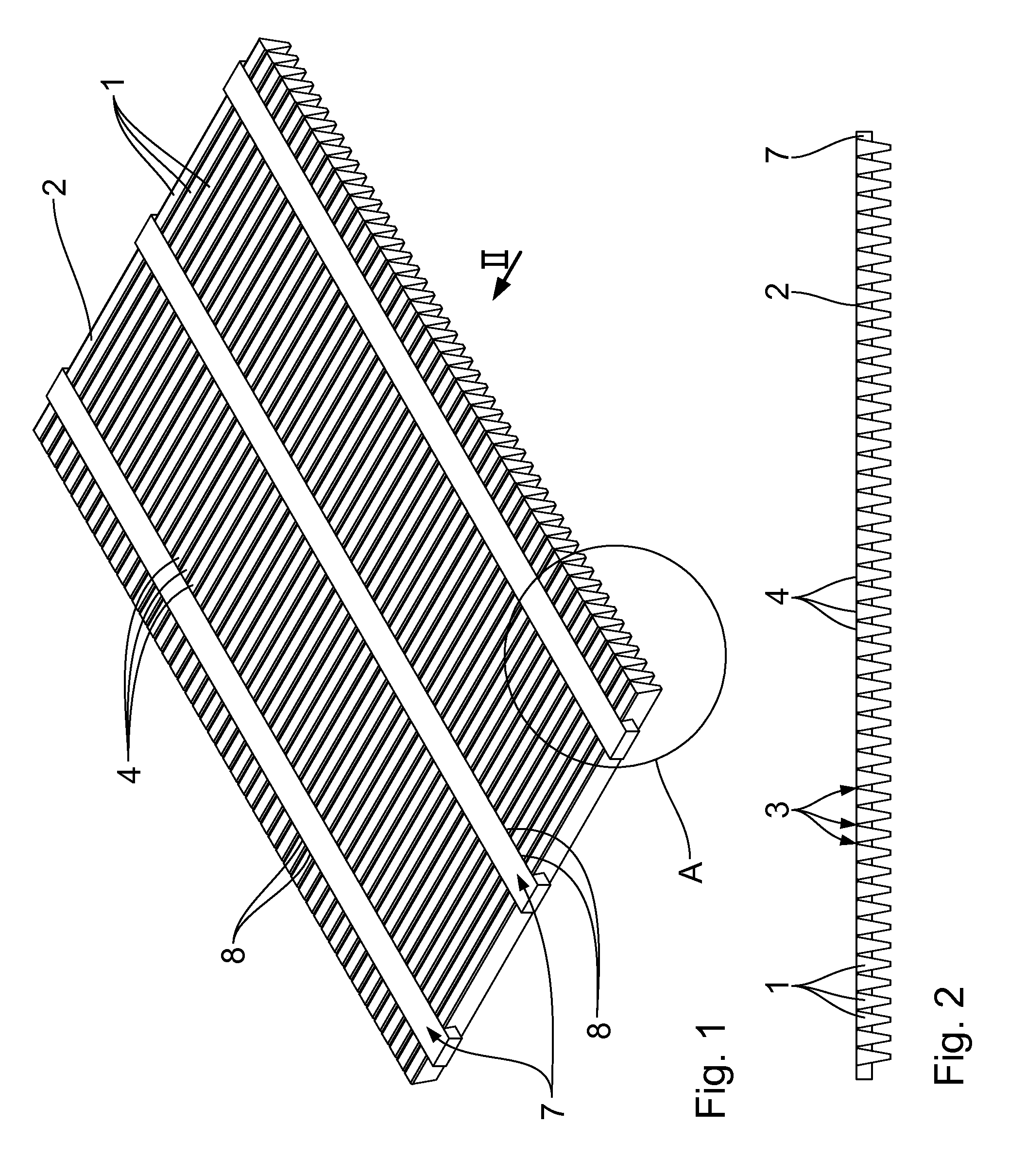
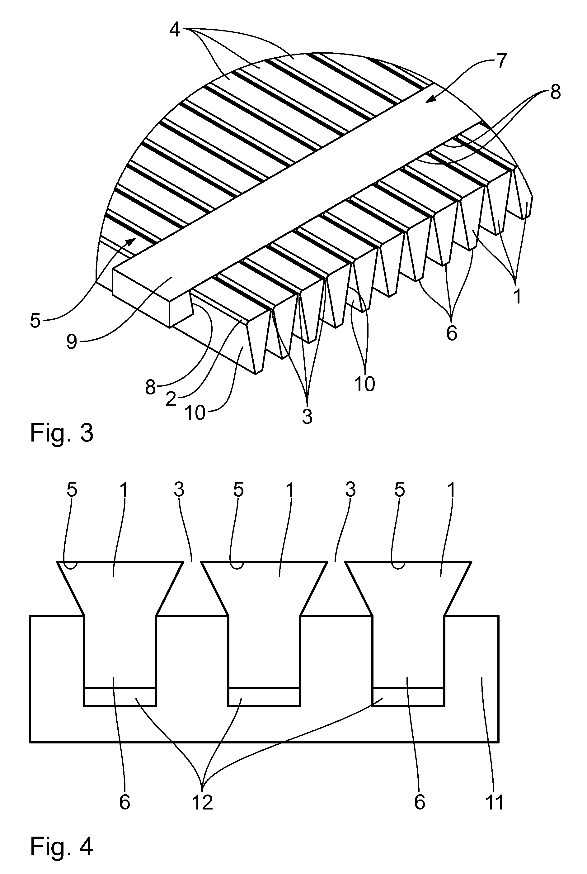
[0028]As becomes clear from the drawings, a slot sieve has a large number of sieve profiles 1 arranged in parallel next to one another, the longitudinal sides 2 of two adjacent sieve profiles 1 forming a sieve slot 3 in each case. As FIG. 3, in particular, makes clear, the individual sieve profiles 1 are trapezoidal in cross section, the wide base sides 4 being arranged in a common plane and forming the slot side 5 of the respective sieve profile 1 or the slot sieve itself.

[0029]The narrow sides 6 of the sieve profiles 1 form the lower side of the sieve.

[0030]The sieve profiles 1 are held together by carrier profiles 7 extending transverse to them, which are in each case arranged in receiving grooves 8 that align with one another in the base sides 4 of the sieve profiles 1. The contour of these receiving grooves 8 corresponds to the flat-rectangular cross section of the carrier profiles 1, so these are let into the sieve profiles 1 and rest with their outsides 9 remote from the siev...


PUM

PropertyMeasurementUnit
Widthaaaaaaaaaa
Widthaaaaaaaaaa

Abstract

A slot sieve comprises a large number of sieve profiles arranged next to one another, which form a respective sieve slot between their longitudinal sides, and at least two, preferably a plurality of carrier profiles, which extend transverse to the sieve profiles and on which the sieve profiles are fastened. The carrier profiles are arranged in receiving grooves, which respectively align with one another, in the sieve profiles in such a way that the outsides of the carrier profiles remote from the sieve profiles are located in a plane with the slot sides or lower sides remote therefrom of the sieve profiles.

Description

FIELD OF THE INVENTION[0001]The invention relates to a slot sieve comprising a plurality of sieve profiles arranged next to one another, which in each case form a sieve slot between their longitudinal sides, and at least two, preferably a plurality of carrier profiles, which extend transverse to the sieve profiles and on which the sieve profiles are fastened, and a holding device for the production thereof.BACKGROUND OF THE INVENTION[0002]A slot sieve of this type is known through public prior use and generally has a plurality of sieve profiles arranged next to one another, which in each case form a sieve slot between their longitudinal sides. The sieve profiles are trapezoidal in cross section, in this case, the actual sieve slot being configured between the wide base sides.[0003]The individual sieve profiles are connected to one another by carrier profiles which extend transverse thereto, on which the sieve profiles are fastened with their narrow sides, such as are formed by the t...

Claims


Application Information

Patent Timeline
IPC IPC(8): B07B1/12B07B1/46
CPCB01D29/01B07B1/12B07B1/4618B01D29/445
Inventor ZOLLNER, THORSTEN
Owner ZOLLNER THORSTEN
Learn More