Boom slewing actuator system

a technology of actuators and booms, which is applied in the direction of cranes, etc., can solve the problems of limiting the rotational range of the boom, slewing actuator arrangements, and large space occupation of the arrangement, so as to prevent the boom from sliding, easy to install, and increase the rotational range

Active Publication Date: 2011-03-24
EMS TECHNOLOGIES
View PDF11 Cites 1 Cited by
  • Summary
  • Abstract
  • Description
  • Claims
  • Application Information

AI Technical Summary

Benefits of technology

[0012]The present invention safely prevents boom slippage through having an integral brake so that when hydraulic pressure is removed (or lost due to component failure), the boom remains securely locked in place.
[0013]The present invention has a compact design, which may provide a greater amount of rotational range to a boom, is easy to install, and can be easily disassembled for shipping, if necessary.
[0014]The present invention includes several degrees of redundancy in order to prevent a system shutdown in the event of a single component failure.
[0049]The structural system of the invention and its modular construction allow for each component to be easily shipped in conventional and relatively inexpensive fashion and then easily assembled during installation at the intended end use location, or subsequently disassembled for removal to another location. Similarly, maintenance and repairs are substantially simplified. As discussed further below, the features of the present invention result in a slewing actuator system suitable for use on ships, land surfaces or docks, with a more compact design, allowing for a greater amount of rotational range of the boom, and at the same time safely preventing boom slippage, and which securely locks the boom in place when hydraulic pressure is removed.

Problems solved by technology

The total length of the rack governs the amount of rotation and, typically, these arrangements can take up a large amount of space in order to operate.
On some ships, and other loading and unloading locations, there may be a small clearance envelope available in which such an arrangement can be positioned, and this can limit the rotational range of the boom to, for example, 90 degrees in some situations, which may not be sufficient for unloading operations.
There are other problems inherent in such slewing actuator arrangements.
Firstly, slewing actuators are typically manufactured and shipped as integral units, and are not disassembled for shipping from the manufacturing facility to the shipyard or other intended use location, thus making transport by air freight or other standard means expensive and difficult, as the equipment used in these systems is very large, heavy and expensive.
Secondly, such systems can be very difficult to install, particularly when intended for use on ships, as they are typically affixed to the ship deck by kingpin bushing arrangements mounted to the ship deck, in which a vertical pin is positioned through a key opening, to the hull.
However, achieving such compatibility can be difficult since these are each usually fabricated by different manufacturers to very tight tolerances.
Thirdly, conventional slewing actuators have a limited number of specific sizes available, often leading to extremely large, over-designed actuators, when the ideal size would have been in between two available sizes.

Method used


Image

  • Boom slewing actuator system
  • Boom slewing actuator system
  • Boom slewing actuator system

Examples


Embodiment Construction

[0061]The invention will be described for the purposes of illustration only in connection with certain embodiments; however, it is to be understood that other objects and advantages of the present invention will be made apparent by the following description of the drawings according to the present invention. While a preferred embodiment is disclosed, this is not intended to be limiting. Rather, the general principles set forth herein are considered to be merely illustrative of the scope of the present invention and it is to be further understood that numerous changes may be made without straying from the scope of the present invention.

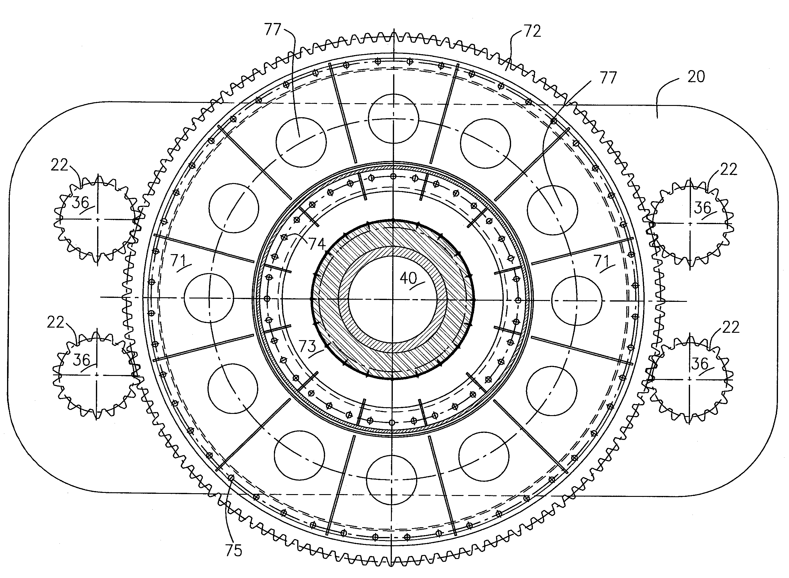
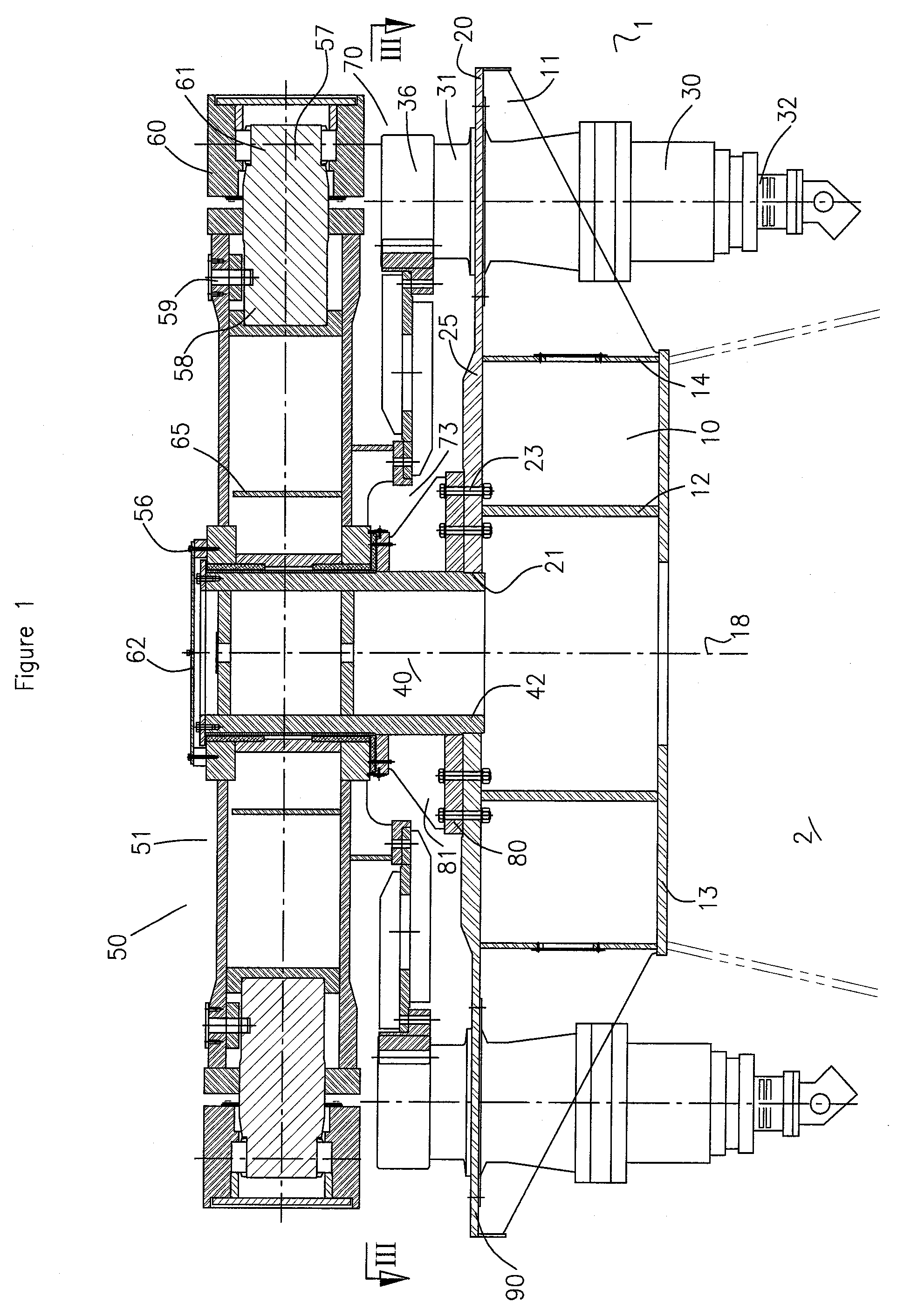
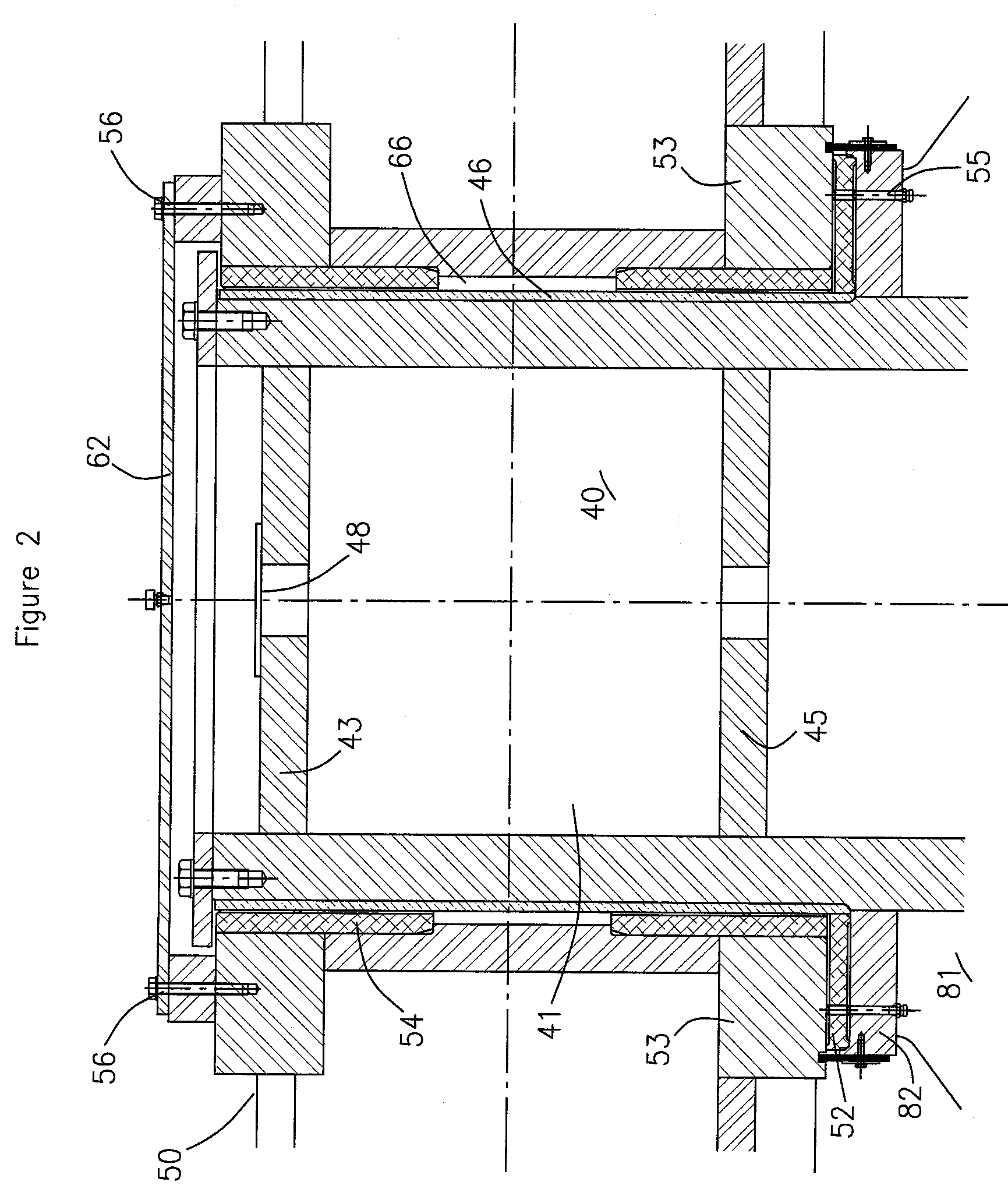
[0062]Referring to FIG. 1, a first exemplary embodiment of the boom slewing actuator system 1 of the invention is shown in an operational position. The slewing actuator system 1 comprises a pedestal 10, having an inner circular wall 12, and an outer wall 14, preferably having a cross-sectional configuration of a regular polygon, the pedestal 10 being m...


PUM


Abstract

A slewing actuator system for rotating a boom structure comprises a cylindrical support member having lower and upper ends; a drive mounting member; gearing means comprising a gear assembly and at least one gear drive fixable to the drive mounting member and operatively connected to the gear assembly; and a boom support means to releasably secure the boom structure and operatively connectable to the gearing means. In an operating position, the boom support means is mounted proximate the upper end of the cylindrical support member and is rotatable about a substantially vertical axis; the gear assembly is substantially horizontal; and the gearing means imparts rotational movement to the boom support means. The system can include a pedestal surrounding at least part of the cylindrical support member, which can be a tube or kingpin. The compact modular system can be secured to various surfaces including ship decks and land surfaces.

Description

[0001]The present invention relates to a slewing actuator system for use with a boom, particularly for use in unloading cargo materials from a ship.BACKGROUND OF THE INVENTION[0002]Booms for loading and unloading materials, whether on land or ship decks, are known, and typically are secured to a fixed supporting point and rotatable around at least a part of a circle.[0003]Such booms when intended for use secured to the deck of a ship, for use in unloading materials contained on the ship, are typically rotated (slewed) around a point on the deck. This rotating motion of the boom has been traditionally achieved by slewing actuators, with the boom structure typically being connected to the slewing actuator by trunnion pins. Typically, such a structure will slew from 90 degrees to 120 degrees in either direction to discharge material to another ship or on shore. Such range of motion generally relates to restrictions based on the space available on the ship deck, and not by any operation...

Claims


Application Information

Patent Timeline
Patent Type & Authority Applications(United States)
IPC IPC(8): B66C23/84
CPCB66C23/84
Inventor ELDER, JOHN B.SUN, DONG
Owner EMS TECHNOLOGIES
Why Eureka
Try Eureka